


VersaGateway User’s Manual
Document #: 2015006.1.pdf
PAGE 5 of 44
Divelbiss Corporation • 9778 Mt. Gilead Road • Fredericktown, Ohio 43019 • 1-800-245-2327 • www.divelbiss.com
Getting Started
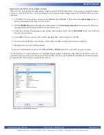
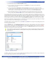
1. In P-Series EZ LADDER Toolkit, from the File Menu at the top, click
PROJECT
then
SETTINGS
. This will open the
Project Set
-
tings
Window. Select
VersaGateway
as the target from the choices. Refer to Figure 1-1. Verify the correct computer COM Port
for communication to the VersaGateway target is selected.
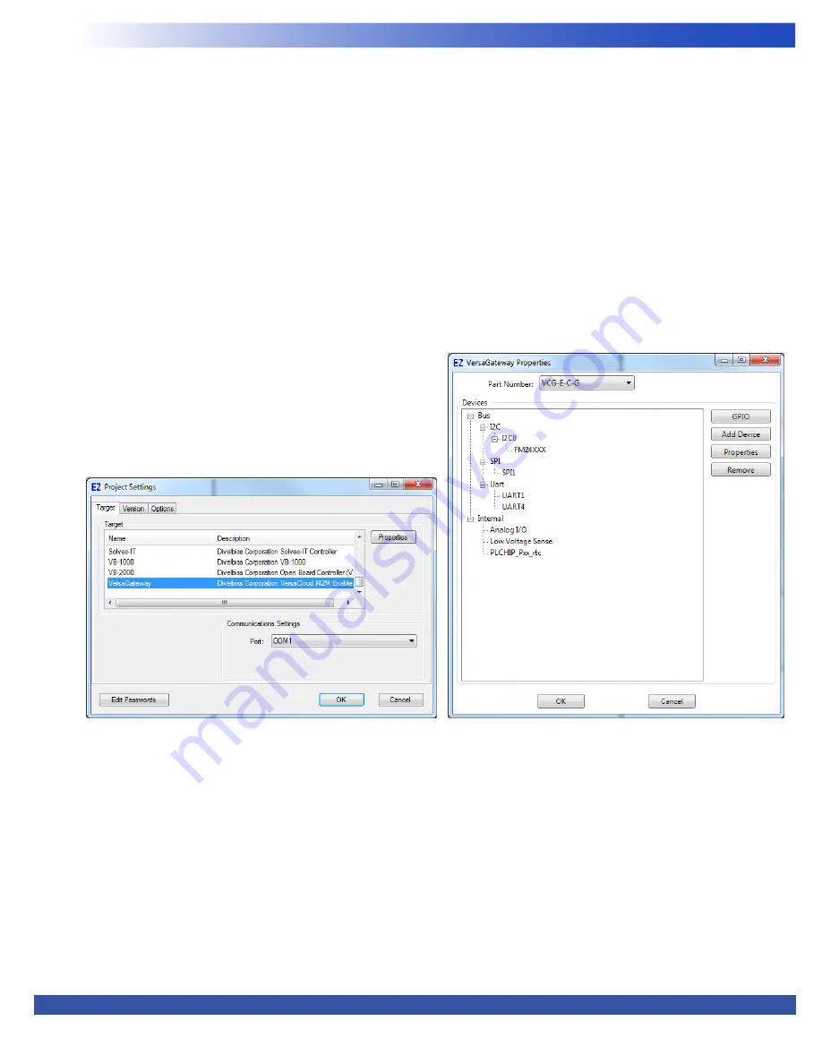
2. Click the
PROPERTIES
button to the right side of the window. The
VersaGateway Properties
Window will open.
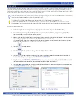
3. Using the Drop-down Part Number select box, select the model of the VersaGatway from the choices. Refer to Figure 1-2.
With the model selected, the Devices pane will update with the currently selected features for the VersaGateway. The
ADD DE
-
VICE
button is used to install and configure additional features such as Modbus or J1939 that are not automatically loaded and
configured. For this example, we will not add additional features at this time. These features may be installed and configured by
re-visiting this window.
4. Click
OK
. This will close the VersaGateway Properties window and save the model selected.
5. Click
OK
. This will close the Project Settings Window, saving the target and installed features for this ladder diagram project.
Note: Any features not shown when clicking
ADD DEVICE
are already installed when the target is selected or are not available.
6. Save your P-Series EZ LADDER Toolkit project by using the
SAVE
or
SAVE AS
from the File Menu at the top of P-Series EZ LAD
-
DER Toolkit.
Figure 1-1 - Project Settings Window
Figure 1-2 - VersaGateway Properties Window


