
VersaGateway User’s Manual
Document #: 2015006.1.pdf
PAGE 37 of 44
Divelbiss Corporation • 9778 Mt. Gilead Road • Fredericktown, Ohio 43019 • 1-800-245-2327 • www.divelbiss.com
Device Features
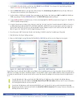
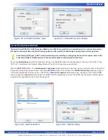
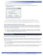
7. Click
OK
to as needed to close each of the open windows including the
VersaGateway Properties
window.
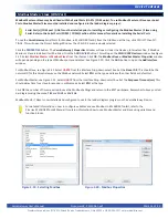
8. Save your ladder diagram using the menu
FILE
and
SAVE
or
SAVE AS
to save the current settings in your program.
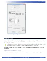
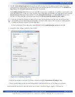
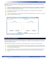
OptiCAN communications is now configured and can be used in the ladder diagram project. OptiCAN uses the OPTICAN_TXNETMSG
and OPTICAN_NODESTATUS function blocks.
Figure 2-34 - OptiCAN Properties
GPS Option
VersaGateway devices support a GPS (Global Positioning Satellite) option (model dependent). The GPS option allows for identifying
the current location of the VersaGateway device (and any equipment connected to it). This is especially useful in the case of locat
-
ing mobile equipment (when combined with VersaCloud M2M ).
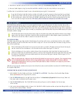
GPS ANTENNA
For GPS supporting models of VersaGateway, the unit ships with a loose - packed puck style antenna that must be installed before
the GPS will be able to function. Refer to Figure 1-5, Item 11 for the location of the Antenna plug-in connection on the VersaGate
-
way.
If the VersaGateway will be installed in an open-air environment or an plastic / fiberglass enclosure, the antenna may be
directly mounted to the VersaGateway. Screw the antenna into position (See Figure 1-5, Item 11).
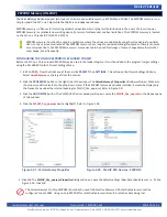
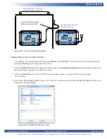
If the VersaGateway is to mounted in a metal enclosure (or any box/enclosure that may block the GPS signal), the
antenna will need to be mounted external to the box / enclosure that could block the GPS signal. Externally connecting
the antenna in this method will require additional cables and a bulk-head fitting (not included). Refer to Figure 2-35 for
mounting method examples.
When mounting antennas, Antennas must be electrically isolated from panel ground / common. If not isolated, damage
to the VersaGateway device will result. When using multiple communication antennas (Wi-Fi, Cellular), sufficient
spacing must be kept between them to prevent interference between them. If interference is suspected, increase the
space between the antennas.
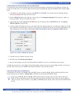
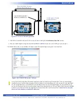
With the antenna properly installed and connected, the GPS option must be installed / enabled in EZ LADDER Toolkit using the
Project Settings Menu.


