


VersaGateway User’s Manual
Document #: 2015006.1.pdf
PAGE 19 of 44
Divelbiss Corporation • 9778 Mt. Gilead Road • Fredericktown, Ohio 43019 • 1-800-245-2327 • www.divelbiss.com
Device Features
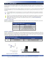
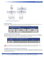
The VersaGateway (model dependent) supports Ethernet communications using an on-board Ethernet port (standard RJ-45). This
port (when enabled) provides Modbus TCP (master or slave) communications. The Ethernet port will operate whether the con
-
nected cable is wired as a patch cable or a cross-over cable. Refer to Figure 1-5 for the location of the Ethernet port (Item 5). Refer
to the VersaGateway Models section for which models support Ethernet.
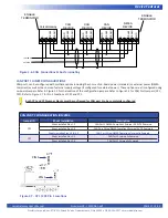
When enabled, the Ethernet port may also be used as the programming port to connect EZ LADDER to the VersaGateway
(monitor and download programs, access the bootloader, etc.).
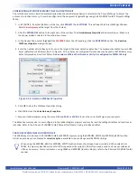
The Ethernet Port for the VersaGateway must be enabled prior to it being used in any capacity. It is
enabled in the
Bootloader
screen. The Bootloader screen will only operate if EZ LADDER is connected to an actual
VersaGateway. The Ethernet port may be shipped from the factory enabled. If not, follow the procedure listed below.
To Access the Bootloader:
1. Verify the target has been configured (see
Configuring the VersaGateway Target in EZ LADDER Toolkit
).
2. Connect the Programming cable (SI-PGM) from the computer to the VersaGateway’s programming port (PGM).
See
Programming Port
in the
Devices Features
section.
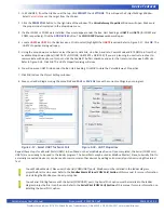
3. Create a small one-rung program with a normally open (direct contact) and an output tied together. You may also open
a pre-existing program for the VersaGateway. EZ LADDER includes a sub-directory
(...EZ LADDER\Kernel Install Start Programs\)which has starter programs for each target to load the kernel. Choose
GetStarted_VCG_X-X-X.dld
. (where XXX is the model of controller).
4. Click the (Compile) button.
5. Click the (Monitor) button to change from the ‘Edit’ to ‘Monitor’ Mode.
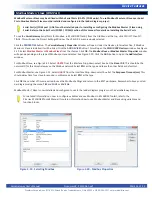
6. Click the (Connect) button to connect to the target. A dialog will appear automatically when no kernel is
loaded. If this dialog does not appear, click
PROJECT
then
BOOTLOADER
.
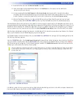
7. Using the menu, click
PROJECT
then
BOOTLOADER.
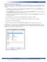
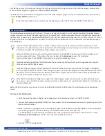
You may see a window momentarily while EZ LADDER connects to
the VersaGateway device bootloader. The Bootloader window will open. See Figure 2-9.
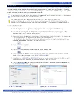
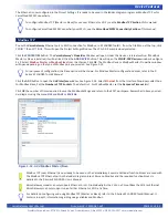
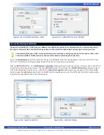
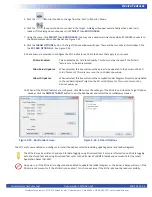
8. Click the
TARGET
OPTIONS
button. The Target Options window will open. There will be two tabs in this window. Click
the
ETHERNET
OPTIONS
tab. See Figure 2-10.
Ethernet Port
Figure 2-9 - Bootloader
Figure 2-10 - Ethernet Options


