38
AUXILIARY CONDENSATE DRAINAGE
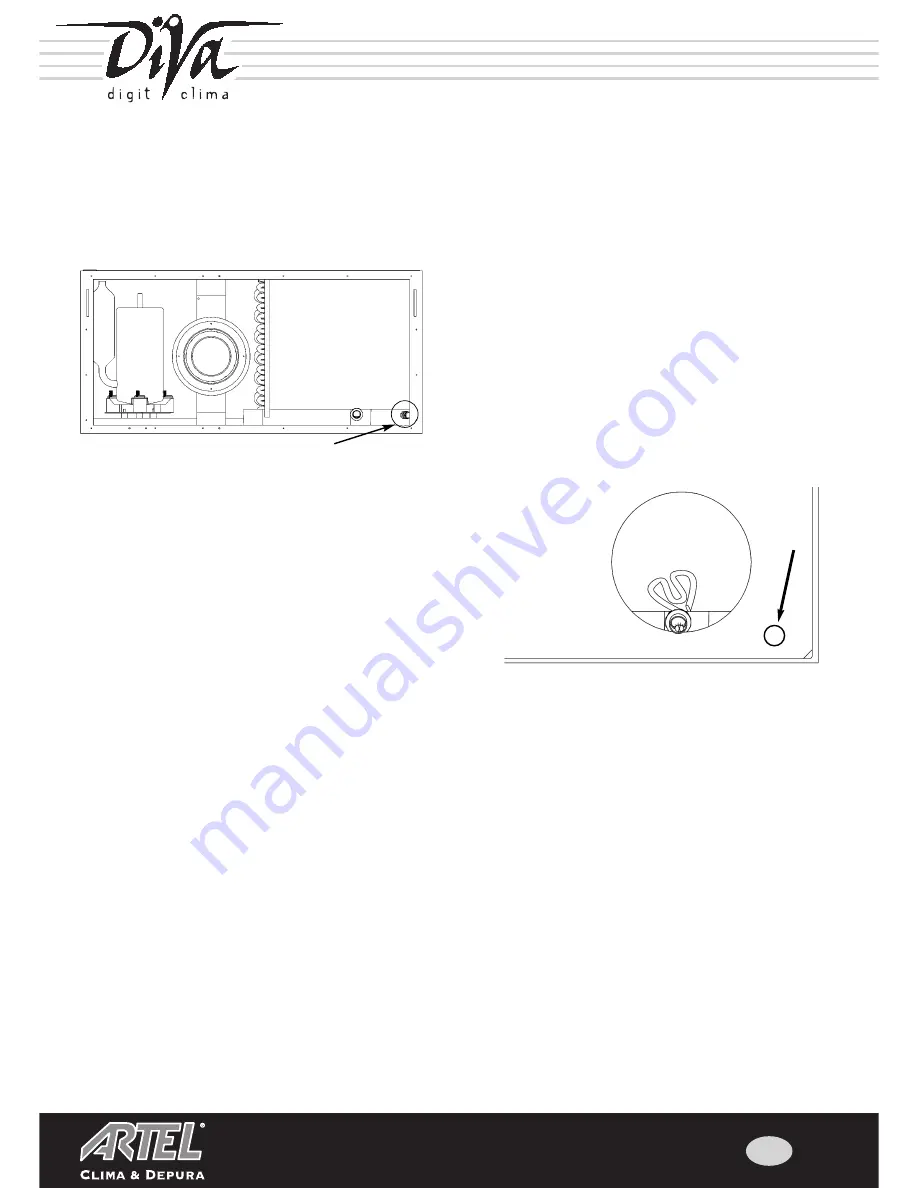
Remove the plug from the condensate drainage nozzle positioned at
the lower right as shown in Figure 1, making sure to avoid cutting
your hands and damaging the heat exchanger.
Whenever crushed or damaged wings are observed, straighten them
before switching the unit on.
Pull the electric heating element completely inside the unit.
N.B. NEVER CUT THE ELECTRIC HEATING ELEMENT.
Make the hole for the passage of the auxiliary condensate drainage
pipe in the rear panel; it is masked by insulation material that covers
the plate (Figure 2); cut away the covering with a cutter, paying atten-
tion not to damage the surrounding insulation material.
Prepare a recess in the wall where the unit will be installed in order to prevent the condensate drainage pipe from raising the air
conditioner and preventing the correct elimination of water; whenever the unit rests on a glass surface, insert adequate vibration-
damping shims to prevent both the vibration of the structure and the crushing of the condensate drainage pipe.
CONNECT TO THIS RUBBER PIPE AN EXTENSION PIPE THAT PERMITS THE EXCESS CONDENSATE CREA-
TED BY THE UNIT TOWARDS A SPECIAL DRAIN OR INTO A TEMPORARY COLLECTION TRAY THAT MUST
BE REGULARLY CHECKED AND DRAINED
.
IMPORTANT: incorrect installation can cause water leakage along the wall.
Whenever the installation of auxiliary condensate drainage is not foreseen, never remove the plug from the inside of the air condi-
tioner.
N.B.: once this plug is removed, water flows freely from the tray and can damage both the unit and the wall.
Pressing firmly, insert the rubber pipe into the condensate drainage nozzle making sure that it is tightly connected
and then reassemble the unit's rear panel.
Fig. 1 (rear view) - condensate plug position
Fig. 2 (rear view) - preparation of hole for pipe
The first thing to do is remove the five screws in the rear panel's lower right corner near the auxiliary condensate
drainage.
When this panel is returned to position, make sure to return these screws to their original positions; the use of screws of insuffi-
cient length can cause serious damage to the unit..
Summary of Contents for RDW 9RN
Page 20: ...40 Cod 000495 NOTE ...


