background image

Directed Digital System MIT4

© 2015 Directed. All rights reserved.

8

Press the:
• 

Lock

 button on the aftermarket remote* to shut 

the vehicle Off and lock the doors.

• 

Trunk

 button on the aftermarket remote to lock the 

doors and enter idle mode.

PANIC

OR

Press Lock to shut vehicle Off 

or Trunk to enter IDLE mode

14:36

* Your aftermarket remote may differ from the model shown in the illustrations.

Idle mode (automatic transmission only)

1

Stop the vehicle in a safe parking spot and put the 
gear in 

Park

 (P).

Put 

gear in 

Park

2

Press the 

Remote Start

 button on the transmitter.*

The parking lights will flash once to indicate the 
vehicle is now in 

Idle Mode

.

Parking lights flash x1

&

Press Remote 

Start button*

14:36

3

Turn ignition OFF and remove the key from the 
ignition barrel.

START

Key OUT

ON

OFF

START

Key IN

ON

OFF

START

Key IN

ON

OFF

START

Key IN

ON

OFF

4

It is safe to leave the engine running and exit the 
vehicle with the factory key in hand.

Note

: We recommend that you always lock the doors 

of your vehicle when leaving it unattended.

Exit vehicle

WITH KEY

* Your aftermarket remote may differ from the model shown in the illustrations.

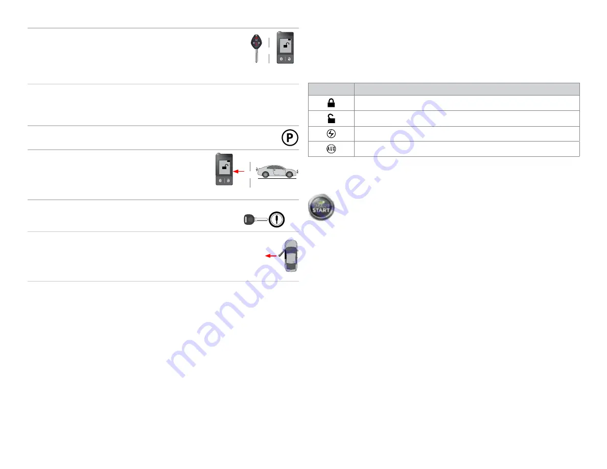
List of available commands

Note that the information below is for Viper, Clifford and Python models. Icons and 
commands may differ depending on the remote brand and model purchased. Refer 
to your authorized installation center for more information.

Button(s)

Actions

Press & hold for 1 second to lock.

Press & hold for 1 second to unlock.

Press & hold for 1 second to remote start.

Press & hold for 5 seconds to activate the trunk release (optional).

* This output is configurable. see your authorized installation center for more information.

SmartStart compatible

This system is compatible with Directed SmartStart 3.0. For a complete list of 
supported features, please visit www.mysmartstart.com.

What is SmartStart?

Now you can remote start, lock and unlock your car just by pushing a button on your 
smartphone; using the SmartStart App from Directed, the leader in vehicle security 
and remote start. The simple graphical interface gives you control over the following 
features of your installed remote start or security with remote start system: 
•  Lock/Arm
•  Unlock/Disarm
•  Remote Car Starter
•  Trunk Release
•  Panic
•  Aux Channels

You can also control multiple vehicles – great for families – and assign more than 
one user to control a vehicle. It's easy with SmartStart! But, this is only the beginning! 
SmartStart is loaded with additional features including GPS tracking, SmartSchedule, 
vehicle status, roadside assistance, home control, parked car finder and more.
3.0 enables a "Cloud-Connected Car" like never before, providing an entirely new 
level of 2-way interaction with your vehicle. Connectivity is managed through the 
Directed Cloud Services (DCS) network linking car, app, end user, and the Internet.

For more information, visit www.mysmartstart.com.

Summary of Contents for MIT4

Page 1: ...intended for installation by a professional installer only Attempts to install this product by a person other than a trained professional may result in severe damage to a vehicle s electrical system a...

Page 2: ...type 2 13 Installation type 3 15 Installation type 4 17 Connecting the module 20 Important 20 Manual or automatic transmission selection 20 Optional sensors 21 RF kits 21 When used in conjunction with...

Page 3: ...peration may result in property damage personal injury or death Except when performing the Safety Check outlined in this installation guide 1 Never remotely start the vehicle with the vehicle in gear...

Page 4: ...icles 2015 2014 2012 2011 2010 2009 2008 2007 2006 PK Immobilizer Bypass Data No Key Req d RS RAP Shut Down Retained ACC Power RS SmartStart 3 0 Compatible RS Tach RPM Output SS Entry Monitoring ALL D...

Page 5: ...rown Relay 1 N O No Connection Auxiliary output harness H2 16 pin black connector Conn Pin Color Description H2 1 Violet Brown No Connection H2 2 Yellow Black No Connection H2 3 Orange Black No Connec...

Page 6: ...C501 harness H4 8 thick gauge wires optional Conn Pin Color Description H4 1 Pink White Ignition 2 Flex Relay Output 3 H4 2 Red White Fused 30A Ignition 2 Flex Relay Input H4 3 Pink Ignition Output Al...

Page 7: ...for starter kill and antigrind connections All adapters are displayed from the wire side unless specified otherwise 3 1 2 4 5 6 7 White 4 White 8 thick gauge wires MC501 1 2 2 3 4 5 11 12 13 8 9 6 7...

Page 8: ...tput Pink 3 12V Input Red 4 12V Input Red 6 2 Starter Input Key Side Green 7 Starter Output Car Side Violet 8 Ignition Red or Black White pin 2 12V White pin 1 Driver Door Trigger Lt Green pin 6 Clutc...

Page 9: ...ont view Junction Block rear view Driver Kick Panel Hood Pin HS CAN High Red pin 6 HS CAN Low Black pin 14 OBDII Diagnostic Connector under Driver Dash connector side view 16 8 9 1 7 6 5 13 14 15 12 4...

Page 10: ...hick gauge wires MC501 Accessory 1 Output Orange 5 Accessory 2 Output Orange 5 Ignition Input Output Pink 3 12V Input Red 4 12V Input Red 6 3 Starter Input Key Side Green 7 Starter Output Car Side Vio...

Page 11: ...ition Green 2 Ignition Switch 6 White Left side of Steering column Power 12V White 1 Ignition Switch 6 White Left side of Steering column Starter Pink 5 Ignition Switch 6 White Left side of Steering c...

Page 12: ...onnector 22 pin white at Driver Kick Panel besides fuse box Lock Green pin 22 Unlock Lt Blue pin 11 Accessory Yellow pin4 12V White pin1 Ignition Green pin2 Starter Pink pin5 Ignition Switch Connector...

Page 13: ...nition Switch 6 White Left side of Steering column Power 12V Blue Yellow 1 Ignition Switch 6 White Left side of Steering column Starter Black Yelllow 5 Ignition Switch 6 White Left side of Steering co...

Page 14: ...6 White Left side of Steering column CAN2 High Red 6 Data OBDII connector 16 Black Drivers Under Dash CAN2 Low Black 14 Data OBDII connector 16 Black Drivers Under Dash Parking Lights Green White 2 C...

Page 15: ...ft side of Steering column Ignition Red 2 Ignition Switch 6 White Left side of Steering column Power 12V Blue Yellow 1 Ignition Switch 6 White Left side of Steering column Starter Black Yelllow 5 Igni...

Page 16: ...White 2 Ignition Switch 6 White Left side of Steering column Power 12V Blue Yellow 1 Ignition Switch 6 White Left side of Steering column Starter Black Yelllow 5 Ignition Switch 6 White Left side of...

Page 17: ...ity Connector Nb pins Conn color Location on vehicle Eclipse 2006 12 Accessory 1 Blue Red 4 Ignition Switch 6 White Left side of Steering column Accessory 2 Blue Black 6 Ignition Switch 6 White Left s...

Page 18: ...ower 12V Blue Yellow 1 Ignition Switch 6 White Left side of Steering column Starter Black Yelllow 5 Ignition Switch 6 White Left side of Steering column Keysense Blue Red 6 Key Switch 7 White Left sid...

Page 19: ...ocating components for type 4 Ignition Switch Key Sensor Blue Red open Open this wire with a relay set for Ground When Running Ignition Switch left side of steering column Eclipse Eclipse Spyder white...

Page 20: ...are shipped ready to use with a manual transmission the yellow loop is untouched If the loop is cut after power has been applied it is necessary to cycle power to the main module via the white 12 pin...

Page 21: ...are available Please follow the instructions included with the kit for appropriate installation and programming information When flashing the Directed Digital System make sure to pick the remote you...

Page 22: ...be connected LAST Solid 4 Turn the Ignition ON using the key START Key OUT O N OFF START Key IN O N OFF START Key IN O N OFF START Key IN O N OFF 5 The LED turns ON green for 3 seconds and shuts off...

Page 23: ...detected Check the Tan Tan Black wire connections Wake up the data bus by turning the ignition on and try again Some installation types do not need this connection External module synchronization LED...

Page 24: ...LED turns ON solid red Solid Solid Release Hard reset Warning Against Executing a Hard Reset A hard reset will revert the flashed firmware back to its default settings Depending on the installation s...

Page 25: ...ations To program Virtual Tach 1 After the install is complete remote start the engine The programming operation may require 3 cranks of the starter before the engine starts and runs Do not turn off t...

Page 26: ...ASSUMES NOR AUTHORIZES ANY PERSON OR ENTITY TO ASSUME FOR IT ANY DUTY OBLIGATION OR LIABILITY IN CONNECTION WITH ITS PRODUCTS DIRECTED DISCLAIMS AND HAS ABSOLUTELY NO LIABILITY FOR ANY AND ALL ACTS O...

Page 27: ...on ready mode 1 While the vehicle is running put the gear in Neutral N Put gear in Neutral 2 Depress the vehicle s foot brake Depress brake pedal 3 Apply the emergency brake Apply emergency brake 4 Re...

Page 28: ...old for 1 second to remote start Press hold for 5 seconds to activate the trunk release optional This output is configurable see your authorized installation center for more information SmartStart com...

Page 29: ...e Note If the parking lights do not flash 5 times you have not entered manual transmission sequence and will need to repeat steps 1 to 5 Parking lights flash x5 6 Turn ignition OFF and remove the key...

Page 30: ...our authorized installation center for more information Button s Actions Press hold for 1 second to lock Press hold for 1 second to unlock Press hold for 1 second to remote start Press hold for 5 seco...

Reviews: