background image

1

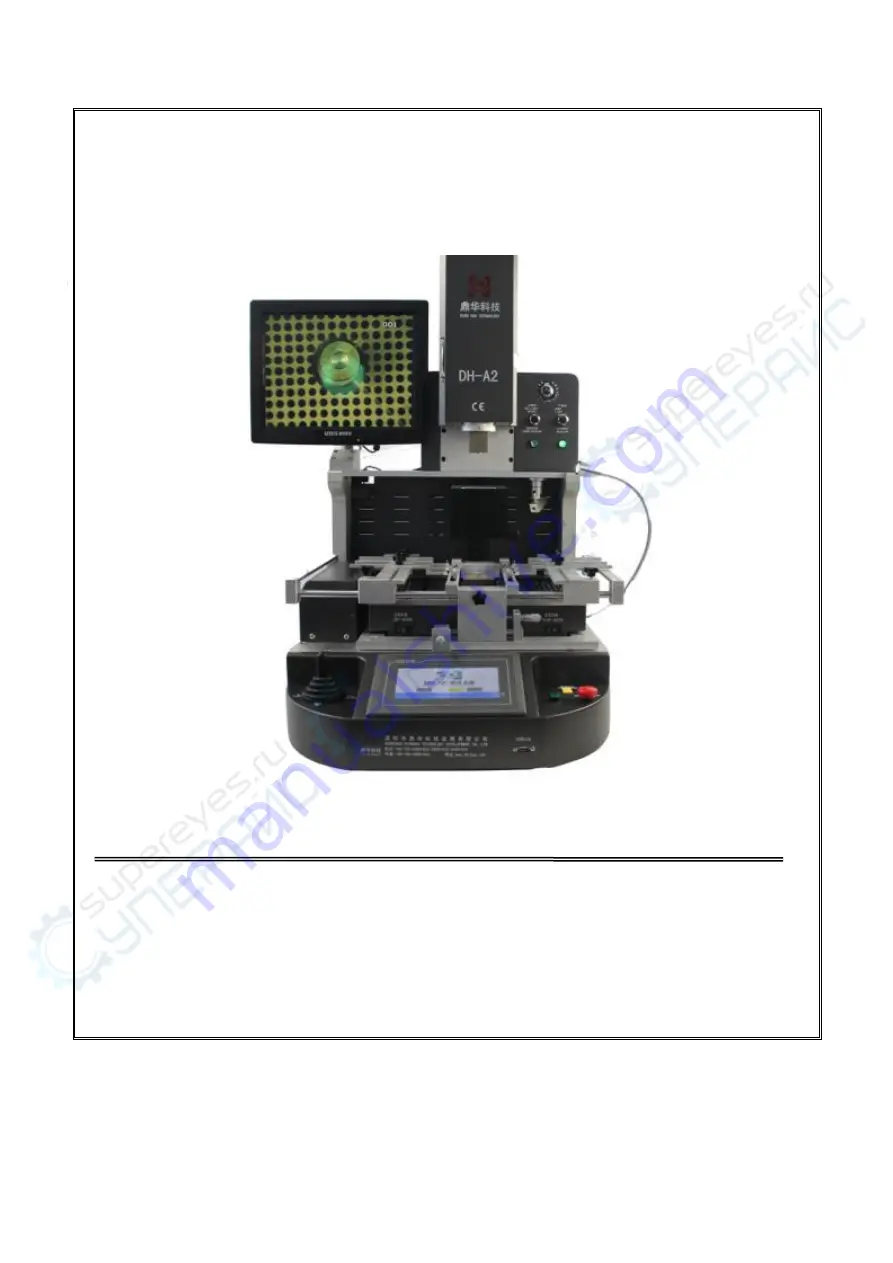
DH-A2 BGA Rework Station Manual

ADD:

4th Floor

Buliding 6B, Shengzuozhi Technoilogy Park

Bao’an District,

Xinqiao

Shajing Town, Bao’an District, Shenzhen, Guangdong

China

Tel:

0755-29091633/29091833

Fax:

0755-29091622

Website:

www.sinobga.com

E-mail:

[email protected]

深圳鼎华科技发展有限公司

Shenzhen Dinghua technology Development Co.,Ltd

Summary of Contents for DH-A2

Page 1: ...Shengzuozhi Technoilogy Park Bao an District Xinqiao Shajing Town Bao an District Shenzhen Guangdong China Tel 0755 29091633 29091833 Fax 0755 29091622 Website www sinobga com E mail dh smt hotmail com 深圳鼎华科技发展有限公司 Shenzhen Dinghua technology Development Co Ltd ...

Page 2: ...r supply C Safety Precaution D Structures and Specifications 1 Structures 2 Functions 3 Main parameters E Setting F Operations G Usage of external couple H Usual temperature reference 1 Welding of lead BGA 2 Welding of lead free BGA I Precautions Attach Packing list ...

Page 3: ...ealized the second revolution from traditional hardware combination to integrated control Our products have been exported to Europe America Southeast Asia Australia Africa the Middle East Taiwan and more than 80 countries and regions and established the relatively sales network and terminal services system We are becoming the pioneer and guide of SMT welding industrial and our products have been a...

Page 4: ...e spray liquid or flammable gas near the repair station 6 Do not try to modify rework station otherwise it will cause fire or electric shock 7 Electrical box has the high voltage components do not attempt to disassemble 8 If the metal objects or liquids fall into the repair station when it works immediately disconnect the power unplug the power cord until the machine to cool down then completely r...

Page 5: ...ng when working Bottom heater hot air nozzle Control the hot air more evenly IR preheating zone Preheating the PCB board Top heater Top heater hot air nozzle LED lamp Bottom hot air nozzle IR preheating area IR controller Workbench X axis fine tune Work bench Y axis fine tune Bottom nozzle height controller Emergency stop Laser switch Screen Display Cross Cooling fan Clip controller Outer temp Sen...

Page 6: ...n off the laser Press the button Start Heat automatically Press the button LED lamp switch LED switch Press the button Optical positioning structure Transmit the image to the displayer Pull it out Cross flow fan Cooling the PCB board after complete the work Clip controller Adjusting the clip Hold by hand Fastener Fasten the supporter in X axis Rotate the handle USB connector Transfer files Outer t...

Page 7: ...controls up and down Massive storage of temperature curves which are accessible at any time according to different BGA Curve analysis setting and adjustment are also accessible via touch screen Three heating areas adopt independent PID calculation to control heating process to enable more accurate temperature 8 It uses high power cross flow fan to enable fast cooling of PCB board and prevent PCB f...

Page 8: ... automatically so that the machine will not be aging after temperature heated up 10 It use rocker controller for controlling the upper heater go up and down freely and it also has the function for zooming the picture CE approved equipped with emergency stop switch and automatic power off protection device when emergency happens E Setting A Introduction of the touch screen operation 1 Switch on the...

Page 9: ...9 Picture 2 3 Click the input box it will appear as follow Picture 3 4 Input the password the default password is 8888 The working interface will appear as follow ...

Page 10: ...the status of the machine now and it will show heating in the heating process 3 this is the optical align distance 4 this the soldering distance 5 the status for the work click here it will has 3 function Dismount Soldering Mounting 3 This is for keeping the temperature constant ...

Page 11: ...color of curve is Baby blue 13 Indicate the practical temperature of upper heater The color of curve is Red 14 Indicate the practical temperature of lower heater The color of curve is Green 15 Indicate the practical temperature of infrared temperature zone The color of curve is dark blue 16 Click it to enter the current program interface as follow which displays the running temperature parameters ...

Page 12: ...eeded please refer to the following procedure 17 If the profile is not suitable for the required welding temperature please click return to the main interface this is the distance for the upper heater descend We usally set it from 190 to 198 but if you can not make sure the distance for the first time you can go to use the to control the upper heater go down until the vacuum sucker touch the bga y...

Page 13: ...e CCD camera we usally set it 20 17 Click it the interface will appear as follow Picture 7 In this interface you can modify and save temperature profiles Users can set the heating time constant time and temperature rate accordingly button to choose the relevant parameter as follow ...

Page 14: ...14 Picture 8 If it is necessary to input new parameters click the box where need to modify it will appear like the picture Picture 9 ...

Page 15: ...be the newest applicable data It will return to the main interface when click button Click the machine will be in the heating condition The running data is just the above current parameters Meanwhile it helps eliminate the displayed curve last time In the normal condition it means the heating process is finished when the temperature speed is zero during the whole running process And then the machi...

Page 16: ...own and you can also set the lowest rotate speed When it appears that fan stops or fan rotate speed lower than it is set during heating when the upper and bottom temperature higher than 300 degrees the system will stop heating system can set advance roar automatically say 10s when it is 10s before the machine finishing heating the buzzer will roar The complete machine switch to cooling state and d...

Page 17: ...ptics position Showing the present position of the top heater 9 Speed showing the speed of the top heater can setting from 3 7 10 Low speed only can set from 1 3 11 Cooling time cooling time you can set to what you need we usally set 200seconds 12 Reset Click it the top heater will go back to back to the top 13 Vacuum Click it the vacuum will on working 14 Manual Up Click it the top heater will go...

Page 18: ...e tin right after the BGA removed and the temperature difference make less damage to the pad It can improve the activity of soldering tin with the flux and is better to clean the soldering tin Pay attention that do not to damage the PCB pad and in order to ensure the reliability of BGA solder try to use some volatile solvents when cleaning the pad such as plate washer water industrial alcohol 4 BG...

Page 19: ...he screen will appear like this Click yes to soldering the chip 8 Soldering 1 Switch on the power select the proper stored temp profile or set for yourself if needed 2 Switch on the laser put the BGA soldering pad center to the laser Fasten the supporter Install the proper nozzle 2mm 3mm larger than the BGA 2 Install the right nozzle 2mm larger than the BGA chip click heating as your chosen data C...

Page 20: ...nd fourth soldering temperature and time or reduce the bottom of the preheat temperature Attention It will cause occur odor in the normal working process In order to assure safe and healthy operation environment please keep ventilation in and out of the room G Outer temperature measurement couple usage A the function of external temperature sensor a To measure actual temperature more accurately du...

Page 21: ...rface like picture five click start then the upper heater begin to heat f Now the screen will show red light blue green three curves Picture seventeen The temperature curve of external couple light blue The current temperature curve of internal couple of upper heater red The current temperature curve of internal couple of bottom heater green Picture seventeen D Use the external couple to adjust th...

Page 22: ... curve and the light blue curve is means the nearer between the temperature of actually heating part and target temperature If it is contrary means the upper heating is not standard 6 If the deviation between these two curve lines is too large proper adjustment to correct is needed 7 Concrete method to adjust is below because of impacted by system technology and environment the deviation is unavoi...

Page 23: ...ly reserve lower heating turn off the upper heating can measure and correct the accuracy of lower heater 9 Statement Turn off the upper heater set the data relevant to upper heater to be 0 Remark This machine take the upper heating time as benchmark to set other segments so when start lower heating alone set the upper temperature to be 0 first segment of upper constant time should be set to larger...

Page 24: ...e 30 30 30 40 20 0 Upper rate 3 3 3 3 3 0 Lower temperature 165 190 215 225 230 0 Constant time 30 30 30 40 20 0 Lower rate 3 3 3 3 0 0 Infrared temperature 180 0 0 0 0 0 Constant time 300 0 0 0 0 0 Infrared rate 3 0 0 0 0 0 38 38 BGA welding temperature setting 1st 2nd 3rd 4th 5th 6th Upper temperature 160 185 205 215 220 0 Constant time 30 30 30 40 20 0 Upper rate 3 3 3 3 3 0 ...

Page 25: ...200 210 215 0 Constant time 30 30 35 45 30 0 Upper rate 3 3 3 3 0 0 Lower temperature 160 180 200 210 220 0 Constant time 30 30 35 45 40 0 Lower rate 3 3 3 3 0 0 Infrared temperature 180 0 0 0 0 0 Constant time 300 0 0 0 0 0 Infrared rate 3 3 3 3 0 0 Above reference temperature are for the leaded products Lead free temperature curve welding 41 41 BGA welding temperature setting 1st 2nd 3rd 4th 5th...

Page 26: ...ng temperature setting 1st 2nd 3rd 4th 5th 6th Upper temperature 165 190 225 245 250 0 Constant time 30 30 35 40 40 0 Upper rate 3 3 3 3 3 0 Lower temperature 165 190 225 245 250 0 Constant time 30 30 35 40 50 0 Lower rate 3 3 3 3 3 0 Infrared temperature 180 0 0 0 0 0 Constant time 300 0 0 0 0 0 Infrared rate 3 0 0 0 0 0 31 31 BGA welding temperature setting 1st 2nd 3rd 4th 5th 6th Upper temperat...

Page 27: ...red heating areas are all controlled by switch and you can choose the bottom heating areas depend on the PCB board size 2 You should set different temperature curves when repair different BGA each temperature should not higher than 300 Lead free rework setting can refer to welding temperature curve of BGA tin bead 3 When demount BGA the cooling fan and vacuum should be set to automatic transmissio...

Page 28: ...ed 6 The machine surface needs to be clean at regular time especially the infrared heating board Avoid the dirt stay on the board because the dirt can lead to heat radiation unnormally bad welding quality and shorten the using time of infrared heating element If the heating element was burn out because of this our company is not responsible for it and no free charge Conclusion In the electric prod...

Page 29: ...on DH A2 SET 1 2 HD display screen PCS 1 3 Suction nozzle SET 1 4 Instruction manual DH A2 COPY 1 5 Hot air nozzle Upper nozzle 31 31 38 38 41 41 Bottom nozzle 55 55 34 34 PCS 5 6 Shaped clip PCS 6 7 Plum knob PCS 6 8 Supporting screw PCS 6 9 Temperature sensor PCS 1 ...

Reviews:

Related manuals for DH-A2