background image

SOL202TIP – SOL808TIP - Tile integrated roof kit manual 


Page 6 of 52 

R02893-1 10/13 

SOLAR 

The  connections  of  a  mounted  solar  collector/collector  array  may  become  excessively 

hot so care must be taken to avoid burns when working around collectors that are ex-

posed to the rays of the sun. 

2


Scope of delivery 

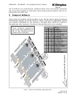
Please check the contents and the condition of your delivery before signing the delivery 

documentation against the content shown in Table 1 and mark as appropriate. Contact 

your  supplier  immediately  for  any  missing  or  damaged  parts.  Claims  for  missing  or 

damaged parts after signing for the delivery documentation will not be accepted. 


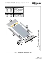
Table 1: Overview of flashing components part 1 

These  mounting  instructions 

only apply to the installation of 
the  in  roof  flashing  and  the 

fixation of the collectors! 

U

se

ab

le

 f

ro

m

 2

 r

o

o

p

it

ch

!

Part No.

Spare No.  Description

P31

74011

left front part

P32

74012

centre front part

P33

74013

right front part

P34

74220

lateral fixation bracket

P35

74222

centre fixation bracket

P36

74111

left lateral part

P37

74113

right lateral part

P38

74001

left collector cover

P39

74002

centre collector cover

P40

74003

right collector cover

P41

74230

connection strip

P42

74090

wooden wedge 600 mm

P43

74091

wooden wedge 1200 mm

P44

74061

left back part

P45

74062

centre back part

P46

74063

right back part

P47

74070

back part connection

SOL202COL

Summary of Contents for SOL202TIP

Page 1: ...Page 1 of 52 R02893 1 10 13 SOLAR SOL202TIP SOL808TIP Tile Integrated Roof Kit Installation Manual ...

Page 2: ...Y 3 1 4 RISK ASSESSMENT 5 1 5 TOOLS REQUIRED 5 1 6 EARTHING AND LIGHTNING PROTECTION 5 1 7 PIPE WORK 5 2 SCOPE OF DELIVERY 6 3 PRODUCT FEATURES AND DESCRIPTIONS 11 4 COLLECTOR CONNECTIONS 11 4 1 SINGLE COLLECTOR PORTRAIT CONNECTION 11 4 2 MULTIPLE COLLECTOR PORTRAIT CONNECTION 12 5 INSTALLATION 13 6 OPERATION MAINTENANCE 49 7 SPARE PARTS 50 8 DECOMMISSIONING 51 9 TECHNICAL DATA 51 ...

Page 3: ...a trained and competent person as defined in the relevant regulations Dimplex does not accept any liability for damage done to persons or property resulting from undue handling and usage of this product All regulations current at the time of installation are to be considered alongside the con tent of this manual as they form the code of best practice The warranty of this product is linked to the a...

Page 4: ...le cordoning Ladders not properly secured against sinking in sliding or falling over may lead to dangerous falls Contact with live electric overhead cables can be lethal If non personal fall protection or fall arrest systems cannot be installed for technical reasons all personnel must be secured by means of suitable safety harnesses Never use damaged ladders e g wooden ladders with split runners o...

Page 5: ... Tools required It is recommended that the below list of tools be used when installing the integrated roof kit 2 people required for installation Measuring tape Hammer Drill Adjustable pliers Angle grinder with stone disc TX 25 x 25mm torque bit Spirit level Plumb line Additional wood as required Pop rivet gun In addition to the above tools it may be required to wear suitable safety gloves upon in...

Page 6: ...g for the delivery documentation will not be accepted Table 1 Overview of flashing components part 1 These mounting instructions only apply to the installation of the in roof flashing and the fixation of the collectors Useable from 20 roof pitch Part No Spare No Description P31 74011 left front part P32 74012 centre front part P33 74013 right front part P34 74220 lateral fixation bracket P35 74222...

Page 7: ...13 19 18 20 Useable from 20 roof pitch Part No Spare No Description P48 74014 front part single collector P34 74220 lateral fixation bracket P36 74111 left lateral part P37 74113 right lateral part P49 74004 single collector cover P43 74091 wooden wedge 1200 mm P50 74064 back part single collector SOL202COL P36 P37 P34 P34 P43 P49 P48 P50 P34 ...

Page 8: ...ont part P33 right front part P34 lateral fixation bracket P35 centre fixation bracket P38 left collector cover P40 right collector cover P36 left lateral part P37 right lateral part P41 connection strip P42 wooden wedge 600mm P43 wooden wedge 1200mm P44 left back part P46 right back part P47 back part connection N 0 0 1 2 P32 centre front part P35 centre fixation bracket P39 centre collector cove...

Page 9: ...SOL202TIP SOL808TIP Tile integrated roof kit manual Page 9 of 52 R02893 1 10 13 SOLAR Table 4 Images of components part 1 5 14 16 P31 P32 P33 P34 P35 P36 P37 P38 P39 P40 P41 P42 P43 P44 P45 17 P46 ...

Page 10: ...SOL202TIP SOL808TIP Tile integrated roof kit manual Page 10 of 52 R02893 1 10 13 SOLAR Table 5 Images of components part 2 18 19 20 21 P47 P48 P49 P50 ...

Page 11: ...ons the collector offers a wide choice of connection options Ensure that no part of the collector array or collector in the array is short circuited by following these instructions When planning the collector array the position of the various connection parts must be in accordance with the diagrams also pay attention to the position of the highlighted sensor pocket Table 6 illustrates the componen...

Page 12: ...ion for single collector only 4 2 Multiple collector portrait connection When installing multiple collectors 2 up to 4 component P03 is used to connect one collector to the next Figure 3 Multiple collector portrait connection The sensor must always be installed at the top of the collector on the connection flow of the system ...

Page 13: ...3 SOLAR 5 Installation NB Ensure all the laths roof battens under the area of the installation are in good condition Replace any damaged week or broken laths and double nail or screw to the rafters Figure 4 Mounted dimensions 220 mm 1225 mm 200 mm 300 mm SOL202COL 2490 mm 4060 mm ...

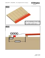
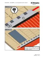
Page 14: ...8TIP Tile integrated roof kit manual Page 14 of 52 R02893 1 10 13 SOLAR Step 2 90 mm 300 330mm P31 P32 P33 P48 Step 1 For the stabilisation of the front parts mount an additional roof bat ten as shown in Step 1 and 2 ...

Page 15: ...202TIP SOL808TIP Tile integrated roof kit manual Page 15 of 52 R02893 1 10 13 SOLAR Step 4 1 6 x P31 Step 3 1 P31 Place the left front part on the roof batten and fix it with 12 sealing screws Step 4 and 5 ...

Page 16: ...anual Page 16 of 52 R02893 1 10 13 SOLAR Step 6 1 2 P31 P32 Step 5 1 6 x P31 Place the centre front part on the roof batten and plug it together with the left front part Step 7 In the case of a 2 collector installa tion please continue with Step 10 ...

Page 17: ...SOL202TIP SOL808TIP Tile integrated roof kit manual Page 17 of 52 R02893 1 10 13 SOLAR Step 8 1 6 x 2 Fix the centre front part with 12 sealing screws Step 8 and 9 P31 P32 Step 7 1 2 P31 P32 ...

Page 18: ...ted roof kit manual Page 18 of 52 R02893 1 10 13 SOLAR Step 10 1 2 3 P31 P32 P33 Step 9 6 x 1 2 P31 P32 Place the right front part on the roof batten and plug it together with the centre left front part Then fix it with sealing screws ...

Page 19: ...P SOL808TIP Tile integrated roof kit manual Page 19 of 52 R02893 1 10 13 SOLAR Step 12 Step 11 1 12 x 2 3 P31 P32 P33 Place the first collector Fit it into the flaps on the front part as shown in Step 13 and 14 ...

Page 20: ...SOL202TIP SOL808TIP Tile integrated roof kit manual Page 20 of 52 R02893 1 10 13 SOLAR Step 14 1 P31 Step 13 1 18 P31 P32 P33 P48 ...

Page 21: ...tep 15 1 Marking for collector Marking for tile P31 Place the collector so that it is aligned with the marking on the left front part Fix the collector on the left outer side with 4 lateral fixation brackets Place the brackets to the collector as shown in Step 17 and fix every lateral fixation bracket with 2 No 5x30mm wood screws ...

Page 22: ...ated roof kit manual Page 22 of 52 R02893 1 10 13 SOLAR Step 18 5x30 mm 5 5 5 5 5 P35 P35 P35 P35 P35 Step 17 4 P34 Place 4 centre fixation brackets to the collector as shown in Step 19 Fix every bracket with 2 No 5x30mm wood screws ...

Page 23: ... SOL808TIP Tile integrated roof kit manual Page 23 of 52 R02893 1 10 13 SOLAR Step 20 P03 P03 Step 19 5 P35 Position 22 x 22mm straight compression fittings on 1st collector loosely before fitting 2nd collector ...

Page 24: ...ently taking the weight off the collector move it to the left ensuring the collector en gages in the centre fixation brackets of the 1st collector Step 22 and into the flaps of the centre front part Step 13 and the loosely fitted compression fit tings Step 20 The distance between the collectors should be about 55mm and this should ensure a neat fit with the centre fixa tion brackets Step 22 ...

Page 25: ...SOL202TIP SOL808TIP Tile integrated roof kit manual Page 25 of 52 R02893 1 10 13 SOLAR Step 24 5x30 mm 5 P35 Step 23 Fix every centre fixation bracket with 2 additional 5x30mm wood screws ...

Page 26: ... 26 P03 P03 Position 22 x 22mm straight com pression fittings on 2nd collector loosely before fitting 3rd collector Step 25 5 5x30 mm 5 5 5 5 P35 P35 P35 P35 P35 Place 4 centre fixation brackets on the right side of the 2nd collector Step 19 and fix eve ry bracket with 2 No 5x30mm wood screws ...

Page 27: ...SOL202TIP SOL808TIP Tile integrated roof kit manual Page 27 of 52 R02893 1 10 13 SOLAR Step 28 5x30 mm 5 P35 Step 27 Repeat steps 20 to 24 ...

Page 28: ...age 28 of 52 R02893 1 10 13 SOLAR Step 30 P01 P02 sensor P36 Step 29 5x30 mm Fix the right outer side of the collector with 4 lateral fixation brackets 4 4 4 4 4 3 P34 P34 P34 P34 P34 P34 Fit collector connections and sensor and pressure test and insulate ...

Page 29: ...l Page 29 of 52 R02893 1 10 13 SOLAR Step 32 6 P36 Step 31 6 1 P36 P31 Fit the left lateral part to the collec tors profile as shown in Step 32 On the lower side the upper perfora tion should be aligned with the col lectors profile as shown in Step 34 ...

Page 30: ... integrated roof kit manual Page 30 of 52 R02893 1 10 13 SOLAR Step 34 1 6 P36 P31 Step 33 6 1 P36 P31 Align the upper perforation with the collector edge Bend the lateral part along the perforation as shown in Step 34 and 35 ...

Page 31: ...TIP SOL808TIP Tile integrated roof kit manual Page 31 of 52 R02893 1 10 13 SOLAR Step 36 1 6 P31 P36 Step 35 1 6 P36 P31 Bend the flap on the left front part so that it fits on the lateral part Step 36 and 37 ...

Page 32: ...ed roof kit manual Page 32 of 52 R02893 1 10 13 SOLAR Step 38 1 6 4x P31 P36 Step 37 6 1 P31 P36 Fix the left lateral part with 4 fixation brackets and a nail and ensure the foam gasket is fitted parallel to the inner side of the fold ...

Page 33: ...ile integrated roof kit manual Page 33 of 52 R02893 1 10 13 SOLAR Step 40 7 3 P31 P37 Step 39 Fit collector connections and pres sure test and insulate P02 P01 Mount the right lateral part in the same way like the left one ...

Page 34: ...P40 P49 P38 P39 P40 P49 Step 41 8 1 6 Important Always check that the opening on the cover fits the ventilation opening of the collector See Step 42a Mount the left collector cover and fit into the collector profile as shown in Step 42 and 43 Important Check the engraved number on the cover Cover for left collector 74001 Cover for centre collector 74002 Cover for right collector 74003 ...

Page 35: ...nt Check the engraved number on the cover Cover for left collector 74001 Cover for centre collector 74002 Cover for right collector 74003 Mount the centre collector cover and fit into the collector profile as shown in Step 42 and 45 Important Always check that the opening on the cover fits the ventilation opening of the collector See Step 42a ...

Page 36: ...nt Check the engraved number on the cover Cover for left collector 74001 Cover for centre collector 74002 Cover for right collector 74003 Mount the right collector cover following the same procedure as for the left and centre cover Important Always check that the opening on the cover fits the ventilation opening of the collector See Step 42a ...

Page 37: ...f 52 R02893 1 10 13 SOLAR Step 48 11 P41 Step 47 11 11 P41 P41 Mount the collection strips between the collectors Just plug them into the collec tor profiles as shown in Step 48 You can use the connection strips in both directions there is no upper or lower side ...

Page 38: ...LAR Step 50 11 11 11 P41 P41 P41 Step 49 11 11 11 Align upper perforation with collectors edge P41 P41 P41 Bend the connection strip along the perforations on the lower side Place the connection strips so that the upper perforation on the lower side is aligned with the collectors edge ...

Page 39: ... Step 52 Additional roof battens Before the mounting of the wooden wedges and the back parts mount additional roof battens to stabilise the back parts and the wooden wedges as shown in Step 52 Step 51 11 11 11 P41 P41 P41 Bend the connection strip along the perforations on the upper side ...

Page 40: ...8TIP Tile integrated roof kit manual Page 40 of 52 R02893 1 10 13 SOLAR Step 54 12 13 P42 P43 Step 53 12 12 13 13 Place the wooden wedges on the upper side of the collectors as shown in Steps 54 and 55 P42 P42 P43 P43 ...

Page 41: ...02TIP SOL808TIP Tile integrated roof kit manual Page 41 of 52 R02893 1 10 13 SOLAR Step 56 5x50 mm 5x70 mm Fix every wooden wedge with 2 No 5x50mm and 5x70mm wood screws Step 55 12 12 13 13 P42 P42 P43 P43 ...

Page 42: ...integrated roof kit manual Page 42 of 52 R02893 1 10 13 SOLAR Step 58 14 20 P44 P45 P46 P50 Step 57 14 6 11 P44 P41 P36 Fit the left back part into the left lateral part and to the collectors profile as shown in Steps 58 and 59 ...

Page 43: ...SOL202TIP SOL808TIP Tile integrated roof kit manual Page 43 of 52 R02893 1 10 13 SOLAR Step 60 14 3x Fix the left back part with 3 No sealing screws P44 Step 59 14 6 P36 P44 ...

Page 44: ...893 1 10 13 SOLAR Step 62 2x 15 14 Fix the centre back part with 2 No sealing screws P44 P45 Step 61 15 14 11 11 P44 P45 P41 P41 Fit the centre back part to the collectors profile as shown in Step 58 In the case of a 2 collector installation please continue with Step 63 ...

Page 45: ...45 of 52 R02893 1 10 13 SOLAR Step 64 16 15 7 2x Fix the right back part with 3 No sealing screws P37 P46 P45 Step 63 16 11 15 7 P41 P45 P46 P37 Fit the right back part into the right back lateral part and to the collectors profile as shown in Step 58 and 64 ...

Page 46: ...IP SOL808TIP Tile integrated roof kit manual Page 46 of 52 R02893 1 10 13 SOLAR Step 66 Step 65 14 6 P44 P36 Fix the left and the right back part with a rivet and a fixation bracket with a nail Step 65 and 66 ...

Page 47: ...d roof kit manual Page 47 of 52 R02893 1 10 13 SOLAR Step 68 17 17 15 14 16 11 11 P41 P41 P47 P47 P44 P45 P46 Step 67 17 17 16 15 14 11 11 Place the back part connections on the back part as shown in Step 68 P47 P47 P41 P41 P44 P45 P46 ...

Page 48: ... SOL808TIP Tile integrated roof kit manual Page 48 of 52 R02893 1 10 13 SOLAR Step 70 Step 69 4x 17 P47 Fix every back part connection with 4 No sealing screws Place foam gaskets along the lateral and back parts ...

Page 49: ... maintenance work on the system ensure that it is safe to do so The solar system must be decommissioned before work can be car ried out Refer to the On Site Guide for a maintenance schedule of the complete system Check for leaks at the collector connections and other connections in the system Also ensure pipe insulation is intact and in good condition Step 71 Finally form the aluminium apron to th...

Page 50: ...11 left lateral part P37 74113 right lateral part P38 74001 left collector cover P39 74002 centre collector cover P40 74003 right collector cover P41 74230 connection strip P42 74090 wooden wedge 600 mm P43 74091 wooden wedge 1200 mm P44 74061 left back part P45 74062 centre back part P46 74063 right back part P47 74070 back part connection P48 74014 front part single collector P49 74004 single co...

Page 51: ...oduct is being recycled local waste disposal laws must be adhered to 9 Technical Data Table 8 Collector technical data Figure 5 Pressure loss collector for anti freeze water mixture 40 60 at a thermal conduct ing temperature of 50 C Weight empty 33 kg Dimensions length 1730mm width 1170mm height 83mm Heat transfer medium SOLHT20 Max op pres bar 10 Tilt angle min 20 max 75 Collector array m 2 4 6 8...

Page 52: ...SOL202TIP SOL808TIP Tile integrated roof kit manual Page 52 of 52 R02893 1 10 13 SOLAR ...

Reviews: