


7
LigHT HARnESS REPLACEmEnT
Tools Required:
Phillips Head Screwdriver
CAUTION:
If unit was operating prior to servicing allow
at least 10 minutes for lights, heating elements and top
panel to cool off to avoid accidental burning of skin.
WARNINg:
Disconnect power before attempting any
maintenance to reduce the risk of electric shock or damage
to persons.
Open the front control cover.
1.
Remove front glass by removing the 2 outer screws
2.
holding the glass clips. (Figure 3)
Remove the log grate by removing the 4 mounting
3.
screws. (Figure 4)
Remove the log set by lifting straight up.
4.
Slide the light assembly slightly out of the insert.
5.
Remove the light bulbs. Hold the socket while un-
6.
screwing the old bulb.
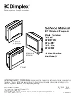
Remove the screws at the back holding the light sock-
7.
ets to the assembly. (Figure 6)
Pull the light sockets out towards the front of the unit.
8.
Disconnect the socket wires from the terminal block
9.
noting the original locations.
Install the new light sockets, securing them with the
10.
removed screws at the back of the assembly.
Reinstall the wires into the original locations.
11.
Hold the socket while screwing in the new bulb.
12.
Reassemble in the reverse order as above.
13.
3-PoSiTion SwiTCH oR HEATER
SwiTCH REPLACEmEnT
Tools Required:
Phillips Head Screwdriver
Flat Head Screwdriver
CAUTION:
If unit was operating prior to servicing allow
at least 10 minutes for lights, heating elements and top
panel to cool off to avoid accidental burning of skin.
WARNINg:
Disconnect power before attempting any
maintenance to reduce the risk of electric shock or damage
to persons.
Open the front control cover.
1.
Figure 6
Figure 7
Remove front glass by removing the 2 outer screws
2.
holding the glass clips. (Figure 3)
Remove the log grate by removing the 4 mounting
3.
screws. (Figure 4)
Remove the log set by lifting straight up.
4.
Lay the insert on its back and remove the 2 screws
5.
securing the switch control cover, which are located on
the bottom of the insert.
Locate the switch to be replaced and disconnect the
6.
wiring clips and connections noting their original loca-
tions. (Figure 7)
!
NOTE:
A flat head screwdriver can be used to gently
pry between the end of the connector and the switch to
release the wires.
Depress the retainer clips on the rear of the switch and
7.
push the switch out of the rear of the cover.
Reassemble in the reverse order as above.
8.
THERmoSTAT REPLACEmEnT
Tools Required:
Phillips Head Screwdriver
Flat Head Screwdriver
CAUTION:
If unit was operating prior to servicing allow
at least 10 minutes for lights, heating elements and top
panel to cool off to avoid accidental burning of skin.
WARNINg:
Disconnect power before attempting any
maintenance to reduce the risk of electric shock or damage
to persons.
Open the front control cover.
1.
Remove front glass by removing the 2 outer screws
2.
holding the glass clips. (Figure 3)
Remove the log grate by removing the 4 mounting
3.
screws. (Figure 4)
Remove the log set by lifting straight up.
4.
Lay the insert on its back and remove the 2 screws
5.
securing the switch control cover, which are located on
the bottom of the insert.
Locate the thermostat control and disconnect the wiring
6.
clips and connections noting their original locations.
(Figure 7)