background image

Assembling The Saw

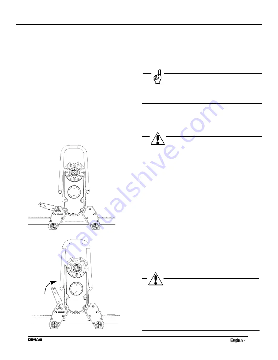
1.  Push retention rollers outward to the release position.

This allows the saw to be placed on the track with
no interference.

2.  Place saw carriage at any location on track.  Make 

sure that the pinion gear meshes properly with the 
track rack and that the saw is down firmly on the 
track. Then push retention rollers inward to the lock 
position.  

3.  Make sure that locking handle is parallel with the 

track and ready to receive the saw head.  In 
vertical cuts it is recommended to place the saw 
carriage with the locking handle pointing towards 
the ceiling to help hold the weight of the head 
when connecting.

Operator’s Manual WS 460

11

3.  Fit the saw body in the saw carriage by lifting the 

saw body into position.  When the saw is placed in 
position, the locking handle moves up into an 
intermediate position.  In this position the saw
remains in the saw carriage without it needing to    
be held.  However, it is not sufficiently held to begin 
cutting.

Remark

With a vertical cut it is usually easier to 

assemble the saw carriage with the handle 
upwards on the track.

4.  To secure the saw, lift the locking handle towards the 

saw until the handle locks in the upright position.

WARNING

Cutting without the saw securely assembled
in the saw carriage could cause significant
injuries and / or could be fatal.

5. When the saw unit is mounted in the saw carriage,

the hydraulic hoses should be fitted.  There are two
types of hydraulic hoses for the saw:

The four thin hoses control the feed motors, i.e. the
saw's travel feed on the track and the 360° 
rotation of the cutting arm.  The two thick hoses 
drive the blade.

The couplings should be wiped clean to reduce the 
risk of contamination before the hoses are fitted. 
Both the thin and thick hoses are locked by turning 
the outer sleeve on the female coupling so that the
groove in the sleeve moves away from the ball.

6. Connect the incoming water hose and the hydraulic

hoses to a hydraulic unit.

WARNING

This machine is only intended for use
together with a DIMAS PP 345, DIMAS  
PP 2325 D, DIMAS PP 2525 D, DIMAS RC 345
and DIMAS Smartbox.  All other use is 
forbidden. The DIMAS Smartbox must be
used with the PP 2325 D and PP 2525 D to 
utilize the power travel feature.

Summary of Contents for Dimas WS 460

Page 1: ......

Page 2: ...s Introduction What Is What Technical Data Cutting capacity Cutting speed m s Cutting speed ft min Assembling Installing Equipment Wall mounting Assembling the saw Mounting the blade Assembling the blade guard Operation Before cutting Sawing Contents 1 ...

Page 3: ... lead base paints Crystalline silica from bricks and cement and other masonry products and Arsenic and Chromium from chemically treated lumber Your risk from these exposure varies depending on how often you do this type of work To reduce your exposure to these chemicals work in a well ventilated area and work with approved safety equipment such as those dust masks that are specially designed to fi...

Page 4: ...roved hearing protection Approved protective glasses or a visor and other essential safety equipment WARNING A large warning triangle with the text Warning signifies that there is a risk of serious personal injury or even death CAUTION A smaller warning triangle with the text Note signifies that there is a risk of minor personal injury or damage to the machine Remark A hand with a raised index fin...

Page 5: ...fitted correctly Never cut without using the blade guard The maximum size of saw blade when starting is 40 1000mm As accessories there are also blade guards for 32 800mm 49 1240mm and 63 1600mm blades Never remove the blade guard without first shutting off the hydraulic unit and ensuring that the blade has finished rotating completely Never disconnect the hydraulic hoses without first shutting off...

Page 6: ...A poorly cooled blade can cause segments to come loose from the blade The water coolant also binds concrete dust Never use a damaged or worn blade Do not use the machine if it is not working properly Regulations for the prevention of accidents and other general safety and occupational health regulations must always be followed Store the equipment in a locked space away from children and adults unt...

Page 7: ...the stresses on the saw and track The reduction of stress has enable Dimas to further optimize the wall saw and make it extremely compact In addition to the compact design the efficiency of cutting and the power applied at the cut has been increased These innovations will help the operator save time during setup cutting and tear down 6 Complete saw equipment consist of Saw Carriage Saw Head Track ...

Page 8: ... the saw are reduced significantly which give straighter cuts and less friction losses between the blade body and the cut 7 6 Blade Guard Guide The blade guard is suspended from this guide When the saw is to be lifted the blade guard guide acts as a handle The blade guard guide also acts as a protective cage for the saw 7 Track The machine is supplied with two tracks one 40 1m and one 90 2 3m 8 Qu...

Page 9: ...he saw to travel Note To stop the saw position the directional control lever vertical or turn the feed speed knob clockwise until the saw stops The power travel comes with a priority flow manifold that includes a pressure relief valve This will stop the saw from feeding when it hits an obstruction such as a track safety stop or if a blade should get pinched in a cut 8 Pressure QD from Priority Flo...

Page 10: ... the arm catches on the base of the mounting 1 Mount track brackets onto surface to be cut using 1 2 12mm size expansion anchors Torque down the mounting nut or bolt to ensure the anchor has good holding strength and will not pull out 2 If the anchor pulls out when being torqued down or when mounting on brick block or hollow precast walls it may be necessary to through bolt with a piece of all thr...

Page 11: ...mum 1 2 size anchors approximately 6 inches from the cut line Fig C The distance between anchors will depend on the track length selected Use 2 or 3 anchors for single length of track The choice of distance between anchors allows the track to be moved longitudinally on the wall without disturbing track mounting brackets 3 Install the track mounting brackets on the anchors with bolts so that the br...

Page 12: ...ier to assemble the saw carriage with the handle upwards on the track 4 To secure the saw lift the locking handle towards the saw until the handle locks in the upright position WARNING Cutting without the saw securely assembled in the saw carriage could cause significant injuries and or could be fatal 5 When the saw unit is mounted in the saw carriage the hydraulic hoses should be fitted There are...

Page 13: ...ick attach blade flange the blade and the outer blade flange together 4 Hang the blade and blade flange assembly on the cutting arm blade is not shown in the figure 5 Carefully rotate the blade until the quick attach blade flange seats onto the cutting arm utilize the power travel feature 6 Press in the blade spindle into the cutting arm at the same time as the blade is rotated carefully When the ...

Page 14: ...uard over the blade and hang the guard in the blade guard guide on the saw Exercise care so that the runners on the blade guard are positioned in the slots on the water block 3 Lock the blade guard by pulling the handle out from the guard When the guard needs to be removed press the handle in towards the guard 13 ...

Page 15: ... is determined from instance to instance and depends on factors such as hardness of the concrete amount of reinforcing bar etc Remark When the saw is cutting the water jet from the blade cutting will spray up towards the ceiling 14 Stop Cutting Once cutting is completed rotate the blade from the wall and shut down the blade rotation and the water flow Shut down the hydraulic unit After Cutting Cle...

Page 16: ... oil The new oil is filled through the hole where the oil plug sits The cutting arm contains 4 oz of Dimas Oil 150 a transmission oil of the type EP 150 The oil should be replaced for the first time in connection with the first service and then twice a year A bottle of oil is supplied when the saw is new Remark Remember oil can pose a hazard to health and and the environment Use care and proper pr...

Page 17: ...d Note Do not over tighten the 6mm socket head setscrew This could cause a slight deformity in the eccentric bushing which could cause the plunge portion of the roller to stick Note The upper rollers located directly underneath the saw carriage are fixed and cannot be adjusted Adjusting The Side Rollers The side rollers should be adjusted if side play is observed between the saw carriage and the t...

Page 18: ...rn the eccentric bushings with the supplied adjustment tool until the cam lies tight against the saw head Tighten the top 6mm socket head setscrew Adjust the other side Remove saw head and tighten the lower 6mm socket head setscrews on both sides Grease The Blade Spindle In order for the blade spindle to be fitted as easily as possible it may be necessary to grease the hexagonal blade spindle Note...

Page 19: ...epaired or approved replacement products Under no circumstances will Electrolux be responsible for incidental or consequential damages The responsibility of Electrolux under this warranty is limited to the repair or replacement at our option of defective parts and assemblies at its plant in Olathe KS and Torrance CA and does not cover engines motors pumps transmissions and other trade accessories ...

Reviews: