background image

42 


F2 SCAN: 

The "SCAN" function allows you to perform automatic port scanning of the connected computers. Users 
can switch ports in order to view the corresponding port computer status. 


The SCAN function can automatically scan from current selected port, the scan interval can be set by 
users. 


When scanning, a small window on the screen indicates the current port number. 


Press [Space] to stop scanning, and the KVM switches to the port last scanned. 

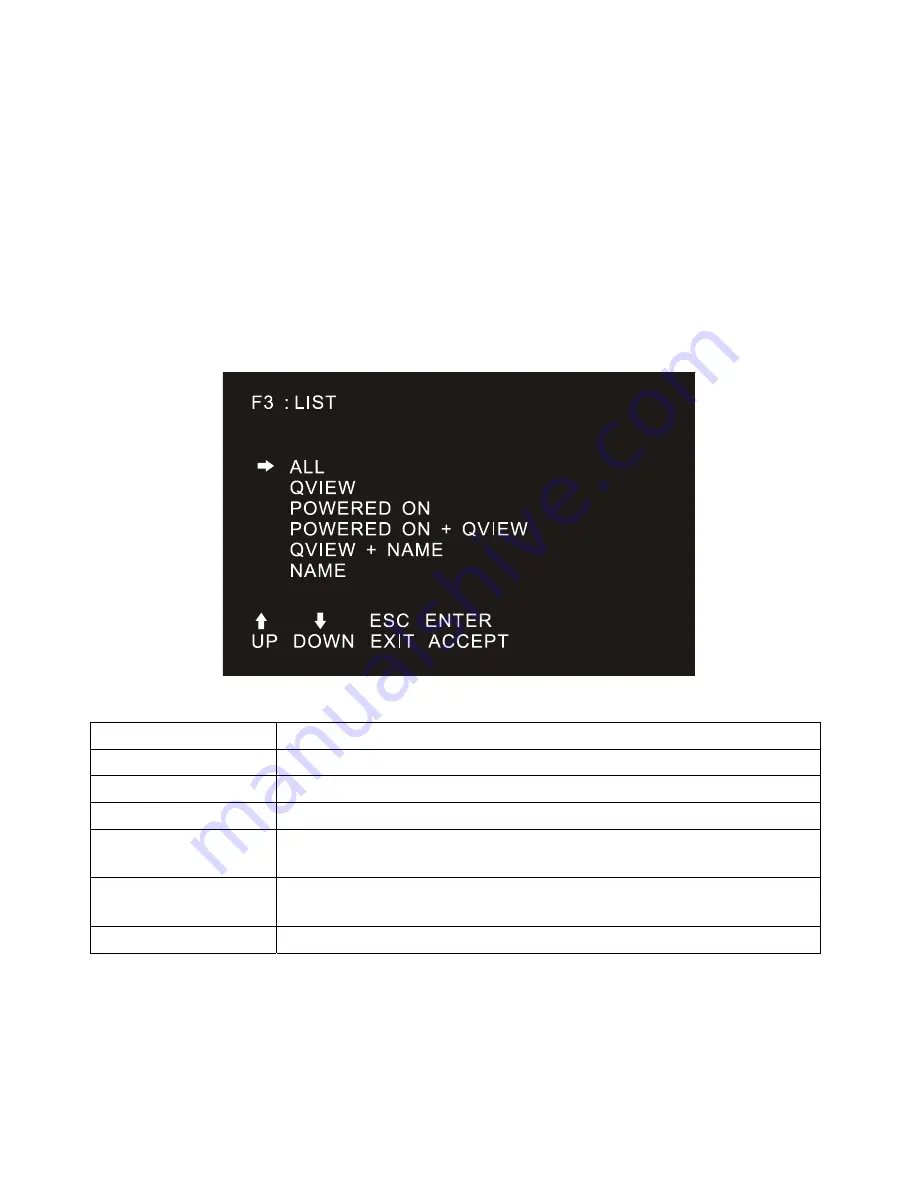
F3 LIST: 

The LIST function lets you broaden or narrow the scope of which ports the OSD displays on the main 
screen. 


Many of the OSD functions only operate on the computers that have been selected for listing on the main 
screen with this function. The choices and their meanings are given in the table below: 

Choice Meaning 

ALL 

Lists all of the ports on the installation. 

QVIEW 

Lists only the ports that have been selected as Quick View Ports. 

POWERED ON 

Lists only the ports that have their attached computers powered on. 

POWERED ON + QVIEW 

Lists only the ports that have their attached computers powered on and 
have been selected as Quick View Ports. 

QVIEW + NAME 

Lists only the ports that have been selected as Quick View Ports and have 
name. 

NAME 

Lists only the ports that have names. 

 
Move the highlight bar to the choice you want, then press [enter]. An icon appears before the choice to 
indicate that it is the currently selected one. 
After you make your choice and press [Enter], you return to the OSD main screen with the newly 
formulated list displayed. 

Summary of Contents for DS-72210

Page 1: ...LCD KVM SWITCH Manual DS 72210 DS 72211 DS 72212 DS 72213 DS 72214 DS 72216 DS 72217...

Page 2: ...anufacturer will not be liable for any damage resulting from incorrect selection of the operating voltage before operation Please be sure that the voltage has been set correctly before use A typical L...

Page 3: ...S 72211 19 inch 16 9 VGA LCD Console LCD screen keyboard and mouse No KVM module DS 72212 1 Port VGA KVM module cable DS 72213 8 Port VGA KVM module with USB PS 2 KVM cables DS 72214 16 port VGA KVM m...

Page 4: ...e 1 Port 8 Port 16 Port 8 Port 16 Port KVM USB PS 2 Cable 1 8m No x 8pcs x 16pcs No No USB KVM Cat5 Dongle No No No x 8pcs x 16pcs Install screw No x 2pcs x 2pcs x 2pcs x 2pcs Quick Installation Guide...

Page 5: ...ions of the LCD KVM 17 Chapter 2 19 Hardware Installation 19 Single Port LCD KVM Cable DS 72212 20 KVM Module Installation DS 72213 DS 72214 21 CAT5 KVM Module Installation DS 72216 DS 72217 22 IP Mod...

Page 6: ...2 SCAN 42 F3 LIST 42 F4 QV 43 F5 EDIT 43 F6 SET 43 OSD ACTIVATING HOTKEY 45 SWITCH HOTKEY 45 SCAN DURATION 46 SET PASSWORD 46 SET SUPER PASSWORD 46 CLEAR THE NAME LIST 47 RESTORE DEFAULT VALUE 47 LOCK...

Page 7: ...ces the front and rear panel components Chapter 2 Hardware Installation This section describes how to install the product and the necessary steps including basic stand alone installation multi switch...

Page 8: ...ered at the same time they are placed in the same bracket and the keys are joined by a plus sign E g Ctrl Alt 1 Numbers indicate the actual operating sequence numbers The diamond symbol indicates that...

Page 9: ...t ways to switch the computer in the installation 1 Use the Port Select button on the front panel of the switch 2 Enter the hotkey combination from the keyboard 3 From the On Screen Display OSD select...

Page 10: ...Port convenient for user to extend USB peripheral keyboard and mouse Unique single installation design It s more convenient to technical installer Control terminal lock function close the LCD display...

Page 11: ...VGA KVM module DS 72214 8 port Cat5 KVM module DS 72216 16 port Cat5 KVM module DS 72217 Computer The following devices must be installed on each computer A VGA video display card USB Type A connectio...

Page 12: ...Optional installation Operation System Operation System Version Windows Windows 2000 XP 2003 2008 Vista 7 10 Linux RedHat 9 0 or higher Fedora and above RHEL AS 4 RHEL 5 SuSE 10 11 1 OpenSUSE 10 2 SL...

Page 13: ...13 Hardware Introduction Front View 17inch 4 3 LCD Console Model DS 72210 19inch 16 9 LCD Console Model DS 72211...

Page 14: ...key 7 Front mounting brackets The LCD KVM can be installed on the cabinet posts with screws 8 Touch Mouse Pad KVM console mouse can control the computer s computer operation 9 Slide rails LCD module s...

Page 15: ...n It is needed if no 8 16 KVM module connected to LCD console 8 Port VGA KVM module DS 72213 8 port VGA Rear View with IP module 16 Port VGA KVM module DS 72214 16 port VGA Rear View with IP module 8...

Page 16: ...16 Front view of the 4 3 screen and 16 9 screen 17inch 4 3 screen 19inch 16 9 screen...

Page 17: ...17 Overall Dimensions of the LCD KVM LCD Console Dimension 462 6 445 45mm...

Page 18: ...18 LCD KVM Dimension LCD Console with KVM 8 16 port KVM module 611x445x45 mm...

Page 19: ...ug all the power cord of the computer with keyboard power on 3 LCD KVM switch packing stuffed with stuffing in the process of delivery to protect the product Attach the protective film and filler to t...

Page 20: ...20 Single Port LCD KVM Cable DS 72212 VGA Single port LCD KVM 1 Port KVM module cable DS 72212...

Page 21: ...fer to the figure for loading and unloading operations 1 Now put this series of products on the appropriate operating platform ready for Screwdriver tools for subsequent use of removable screws Remove...

Page 22: ...ected to the same group of KVM connection port jacks all connected to Port1 or all connected to Port2 2 The IP module is an optional module of the product If the product you purchased does not include...

Page 23: ...ed management of KVM Application over IP control 1 Find the rear of the device expansion slot outside the blank position for installation you need to prepare a screwdriver for removal and installation...

Page 24: ...wo screws that have been removed before 6 After installing the IP module you need to follow the instructions of the IP module to install the software and configure the IP address of the device before...

Page 25: ...h a nut and the fixing nut is welded inside the bending hole at the top of the bracket Install the bracket into the cabinet mounting post on the upper cabinet align the bracket mounting holes with the...

Page 26: ...26 Place the KVM Switch in the installed bracket and secure the KVM Switch cabinet and mounting bracket...

Page 27: ...27 Mounting and fixing in the bracket tail with Lock Ear and Screws from accessory...

Page 28: ...1 Plug your USB keyboard and mouse into the USB console port if 2nd console needed 2 Using a set of KVM cables corresponding to the model plug the VGA connector into the VGA Port of any available VGA...

Page 29: ...If the product you purchased does not contain the module please ignore the related operation in Step 5 3 Before using the IP module please make the appropriate configuration and network debugging afte...

Page 30: ...gure Connect to the upper level switcher 2 The number of computers connected to each level can be freely increased or decreased according to your requirements 3 Between the level of IP module can be o...

Page 31: ...31 KVM Switch Cascade diagram 8 Port DS 23200 2 16 Port DS 23300 2 Note Please connect only one of interface from USB or PS 2 USB is suggested...

Page 32: ...e LCD panel turned up revealing the keyboard the mouse s operating surface 2 The bottom of the keyboard panel has a circular hole you can use your fingers through the circular hole the top of the keyb...

Page 33: ...33 Note If you replace the installation please first plug the keyboard USB interface then put the keyboard module into the limit slot...

Page 34: ...g system does not support hot plug functionality this feature may not function properly Hot Plug Console Port This product also provides keyboard mouse and display hot plug function This product provi...

Page 35: ...ic key serial number you input when the key switch port changes Port Switches the Numeric Keypad Area This area has the numeric keys of 0 9 and RST reset button ENT confirm button the number keys are...

Page 36: ...is the keyboard number 01 16 the keyboard combination hotkey input complete carriage return completed the command transmission KVM switch will switch the corresponding number Of the Port computer If y...

Page 37: ...37 Open Way of LCD Screen OPEN CLOSE...

Page 38: ...ts to bring the instability and may cause damage to the user collision After the brake lock is activated the LCD screen will limit the operation of pushing the slide rail If you want to do the push in...

Page 39: ...rd is set successfully the subsequent login requires the correct administrator user password to enter the OSD menu Interface operation When you enter the setting options some functions may need to be...

Page 40: ...If the number of rows in the list is larger than the number that the screen can display the screen scrolls When the OSD menu is closed a small blue window will appear on the screen showing the port n...

Page 41: ...rt the GOTO function The GOTO function allows you to switch directly to the connection port by typing the port name or its port number 1 To use NAM method move highlight bar to NAME press Enter input...

Page 42: ...sting on the main screen with this function The choices and their meanings are given in the table below Choice Meaning ALL Lists all of the ports on the installation QVIEW Lists only the ports that ha...

Page 43: ...e name of a port Press F5 a pink edit box will appear on the screen Input name and then press Enter the port is set a name and it will also appear on the screen F6 SET SET function settings can be set...

Page 44: ...fore to indicate that the item has been selected The settings are described in the following table Settings Function OSD ACTIVATING HOTKEY OSD Menu Activates hotkey combination selection settings SWIT...

Page 45: ...L CTRL as the OSD menu start hotkey SWITCH HOTKEY It provides you with four hotkey combinations SCRLL SCRLL NUM CTRL CTRL NUM ALT ALT NUM SHIFT SHIFT NUM You can use the keyboard to move cursor to sel...

Page 46: ...d press Enter to select it SET PASSWORD Set new password First enter old password then enter new password and confirm it The new password is set If error occurs the screen will remind users SET SUPER...

Page 47: ...options to restore the initial settings so please be careful to do this When doing this you need to verify the password of the administrator input Y key then press Enter to confirm the operation To c...

Page 48: ...0V 230V phase to phase voltage To prevent damage to your device it is important that all equipment be properly grounded Do not place anything on the power cord or cable and route the power cord and ca...

Page 49: ...and stable Be careful when releasing the latch by pressing the device rails and sliding the unit into the rack The track of the slide rail may clip to your finger After mounting the device to the rac...

Page 50: ...Service life 100 000Hours Nominal Input Voltage 5 0V Keyboard Keyboard Layout Ultra thin US100 key Stand alone Removable keyboard Keyboard language format optional Compatible Microsoft Windows XP WIN7...

Page 51: ...37PIN DB 37PIN DC Jack Male PC Connector KVM Module 1 x VGA DB15 USB PS 2 8 x VGA DB15 Female Blue 16 x VGA DB15 Female Blue KVM Cable 1 2m attached 8x 1 8m 16x 1 8m Power NA 1 x DC Jack Female Networ...

Page 52: ...ey OSD Hotkey Ctrl Ctrl Switch Hotkey Scroll Scroll Num Operating Environment Operating temperature 10 50 C Storage temperature 20 60 C Humidity 0 80 RH No Condensation Physical Properties Housing Met...

Page 53: ...ke appropriate measures Hereby Assmann Electronic GmbH declares that the Declaration of Conformity is part of the shipping content If the Declaration of Conformity is missing you can request it by pos...

Reviews: