background image

27

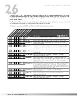
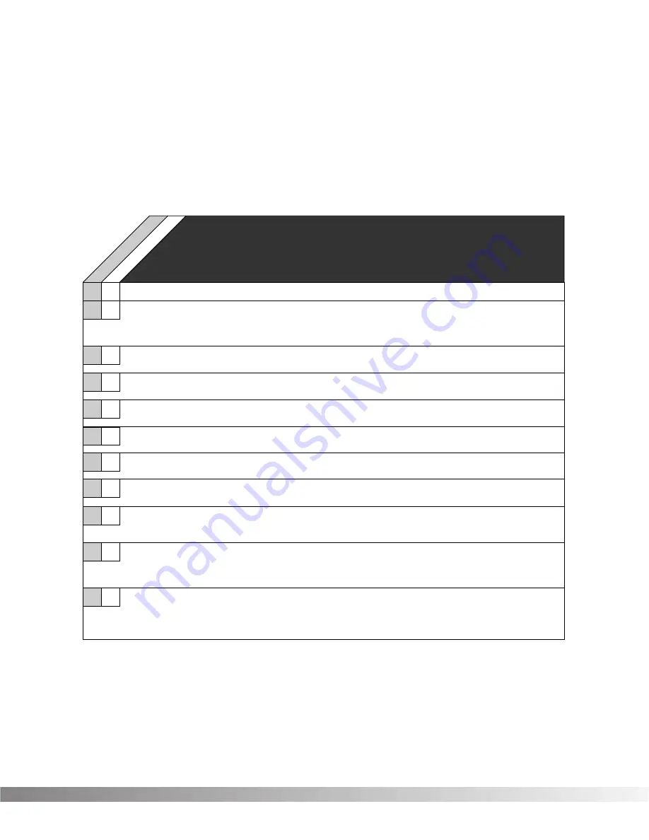
NOISE GATE / COMPRESSOR

Noise gates are particularly useful for preventing mic rumble, wind noise, or hum from getting to tape in your
recordings, or for gating drum kits to prevent mic bleed.

Compression does exactly what its name implies; it compresses the dynamic range of the signal. It does this by turn-
ing signals down as they become louder. After it makes the adjustments, it brings the overall signal back up.   

Compressor

Gate

ThshO

Sets the level at which the gate begins to open at the rate set by ATTACK. Both THSHO and THSHC 
are independent controls. This gives you the option to do nifty stuff like setting THSHO higher than 
THSHC, which could be used to let guitar notes sustain longer while still retaining the noise-gating 
characteristics of the gate when closed.

ThshC

Sets the level at which the gate begins to close at the rate set by RELEASE. Both 
THSHO and THSHC are independent controls.  THSHC cannot be set higher than THSHO.

Thsh

Sets the minimum input level at which the compressor will engage
Ranges from  -27 to 0.

Ratio

Controls the amount of gain reduction applied to the input signal.
Ranges from 1.5 to 40.

Gain

Controls the amount of gain that can be added to a signal after it has been compressed.
Ranges from   0 to  200%

Attack

Controls how quickly the gate or compressor opens after the signal level reaches THSH. 
Varies from 0 to 2 seconds (Noise gate), Fast or Slow (Compressor).

Release

Determines how quickly the gate closes after the signal level falls below THSHC, or how 
quickly the compressor disengages. When used in conjunction with long HOLD settings, this control 
can be used to further prevent stuttering, or to make the closing of the gate less obtrusive. 
Varies from 0 to 2 seconds (Noise Gate), Fast or Slow (Compressor).

Hold

The setting of HOLD determines how long the gate remains open after the signal level falls below THSHC.
Long HOLD settings can be used to prevent the gate from "stuttering", or opening and closing rapidly,
during soft passages when average signal levels are just above or below the THSHC setting.  Varies 
from 0 to 500 milliseconds.

Delay

Sets the amount of Delay before the Gate or Compressor engages.Ranges from  0.1 to 10
milliseconds.

PARAM.

DESCRIPTION

Noise Gate/Compressor

Level

Controls the signal input level fed to the Module. Varies from OFF to 100%.

Attn

Adjusts how far the signal level is lowered (attenuated) when the gate is closed. The higher you set 
ATTN, the lower the noise floor of the source when the gate is closed. Varies from 0% to 100%.

Section 3 - Effects and Parameters

Studio Quad V2 User's Manual

Summary of Contents for STUDIO QUAD V2

Page 1: ...cessor A Harman International Company S DISC PROCESSING User s Manual 1 2 F X E d i t P r o g r a m C o m p a r e C o m p a r e 4 I N 4 O U T M U L T I E F F E C T S P R O C E S S O R S D I S C P R O...

Page 2: ...take it to a dealer for service Disconnect the unit during storms to prevent dam age CAUTION ATTENTION RISQUE DE CHOC ELECTRIQUE NE PAS OUVRIR WARNING TO REDUCE THE RISK OF FIRE OR ELECTRIC SHOCK DO N...

Page 3: ...grams 13 SECTION 3 EFFECTS AND PARAMETERS About Modules and the Effect Charts 14 Digital and Analog Effects List 14 Reverbs 15 Chorus and Flange 18 Phasers 21 Rotary Speaker Simluator Tremolos and Aut...

Page 4: ...l be covered up to a period of one year A Return Authorization number may be obtained from DigiTech by telephone The company shall not be liable for any consequential damage as a result of the produc...

Page 5: ...d to understand when you use the Studio Quad V2 They are 1a Program Number Indicator These three large digits in the upper left corner of the display indicate which Program is currently selected 1b Fa...

Page 6: ...ode module flashes the Input Routing indica tors and the Output Mode module flashes the Output Routing indicators 2 PROGRAM BUTTON Selects Program mode for Program selection The Data Wheel is used to...

Page 7: ...s a Bypass NOTE The footswitch must be plugged in on power up in order for the Studio Quad V2 to detect which type of switch is being used 7 POWER INPUT Connect the included power supply to this jack...

Page 8: ...s for true stereo operation Pan Mute 10 0 5 10 20 30 5 L R Mute L R Mute L R Mute L R 5 4 3 2 1 0 1 2 3 4 5 Pan 5 4 3 2 1 0 1 2 3 4 5 Pan 5 4 3 2 1 0 1 2 3 4 5 Pan 5 4 3 2 1 0 1 2 3 4 5 Pan 5 4 3 2 1...

Page 9: ...od also offers the flexibility of running different channels in line or in an effects loop REMEMBER Outputs can be configured any way you like so don t let any of this input output stuff scare you A W...

Page 10: ...PROGRAM button is dim press PROGRAM once to return to Program mode Use the PROGRAM button to select the Program bank Factory or User Each successive press of the PROGRAM button toggles between the Fa...

Page 11: ...Studio Quad V2 makes it simple If you re not already there switch to Program mode and use the Data wheel to scroll to Factory Program 139 The display reads Press FX EDIT Note the current module being...

Page 12: ...the 9 available output configurations Press parameter button 4 then use the Data Wheel to to set the output level for the program NOTE Make sure you store any changes you want to save before exiting t...

Page 13: ...consistently being changed by a Modifier Storing the Program will store these new Parameter values LINKING A PARAMETER TO A MODIFIER To link a Parameter to a Modifier do the following Press FX EDIT un...

Page 14: ...in the bottom right corner of the screen To adjust the settings of the Dynamic Modifier use the NEXT PAGE and PREV PAGE keys to scroll to Page 10 The display reads Press 2 and use the Data wheel to a...

Page 15: ...hange the character to one you want in the selected position When the correct char acter is displayed in that position press NEXT PAGE The cursor moves one character to the right Using the NEXT PAGE a...

Page 16: ...inputs they can still be used with a mono source such as input one of the Studio Quad V2 The mono source would just be routed to both sides of the Module s inputs Notice how the Dual FX Module mainta...

Page 17: ...bs There are five basic reverbs to choose from 1 Reverb Simple straight ahead reverb with only the most basic parameters 2 Dual Reverb Multi dimensional reverb with flexible frequency band splitting c...

Page 18: ...igh the initial room echoes can be heard as discrete echoes followed by smoother room reverberations Set DISPERSION low for a dense cluster of reflections during the early portions of DECAY Varies fro...

Page 19: ...n hearing Delay Group C and Delay Group D Ranges from 0 to 120 milliseconds Decay Controls the length RT60 of the room reverberations This one control could have been divided among Size and Reflection...

Page 20: ...y difference between choruses and flangers is that flangers use less delay and have a feedback Parameter that sends a portion of the effected signal back to the input of the Module When the effected s...

Page 21: ...ls the delay time of chorus voices E H Higher delay time settings produce a more dramatic sweeping sound Ranges from 0 to 60 milliseconds Out A B Adjusts the overall level of chorus voice A or B Range...

Page 22: ...ve voice Flangers are capable of both positive and negative feedback loops so experiment to find the sound you like best Ranges from 99 to 99 WvFrm Selects which waveform the LFO follows Options for t...

Page 23: ...Depth Adjusts the intensity of the phaser effect High settings of DEPTH combined with high settings of FDBCK produce dramatic synth like results Varies from 0 to 100 milliseconds FdBck Controls how mu...

Page 24: ...e in Settings are fast or slow Spread Sets the horn stereo microphone spread Varies from 0 to 100 Doppler Sets the amount of shifted pitch heard in the horn Range is 0 to 50 milliseconds X Over Select...

Page 25: ...t Ranges from 0 to 60 milliseconds Dtn A B Controls the detuning amount for detuner voices A and B Higher detune settings produce a more dissonant sound Ranges from 50 to 50 Dtn C D Controls the detun...

Page 26: ...stereo imaging The higher the setting the wider the image The lower the setting the more monophonic the effect becomes Range 1 to 10 Pan C D Controls the stereo soundfield placement of pitch shifted v...

Page 27: ...voice A delay time is 750 ms Remember each voice in the Module can have any delay time up to 100 of DELAYTIME Ranges from 0 to 100 TapIt DlyC D See Dly A B Ranges from 0 to 100 Out A B Adjusts the ove...

Page 28: ...octave frequencies Boost cut range for each band is from 12 to 12 PARAM DESCRIPTION Equalizers S t e r e o P E Q 3 M o n o P E Q 6 S t e r e o P E Q 6 LoShlv Freq Controls the center frequency of the...

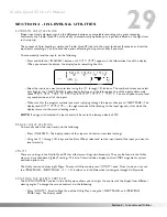
Page 29: ...added to a signal after it has been compressed Ranges from 0 to 200 Attack Controls how quickly the gate or compressor opens after the signal level reaches THSH Varies from 0 to 2 seconds Noise gate F...

Page 30: ...ect Varies from 0 to 30 milliseconds C F Delay Controls the delay time of the Chorus or Flanger voice Ranges from 0 to 40 milliseconds Feedback Controls the fade time of the delay repeats Higher setti...

Page 31: ...t Level will be set to the factory default of 70 MANUAL INPUT LEVELING To manually adjust the input levels do the following Press IN LEVELS The display shows all four inputs and their current level se...

Page 32: ...u using the NEXT PAGE and PREVIOUS PAGE keys The display reads Press 2 and use the Data wheel to select the MIDI Program change number you want mapped Note that the number under STUDIOUSER changes alo...

Page 33: ...t To change the SysEx Device Channel number or MIDI Merge setting do the following Press UTILITY and scroll to Page 3 of the Utility Menu using the NEXT PAGE and PREVIOUS PAGE keys The display reads U...

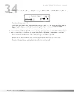
Page 34: ...ump To perform a System Dump do the following Press UTILITY and scroll to Page 5 of the Utility Menu using the NEXT PAGE and PREV PAGE keys The display reads To initiate the dump press 4 The Informati...

Page 35: ...ss UTILITY scroll to page 7 of the Utility page using the Prev Page or Next Page buttons The dis play reads Using the Data wheel you can modify the Reference note anywhere from A 427 to A 453 To exit...

Page 36: ...eliminating any custom settings created by the user The procedure is as follows Press and hold the 1 Parameter button while powering up to the Studio Quad V2 Release the 1 Parameter button after an as...

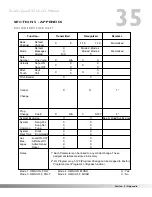
Page 37: ...s Aux Mes sages Local ON OFF All Notes Off Active Sense Reset Notes Mode 1 OMNI ON POLY Mode 2 OMNI ON MONO Mode 3 OMNI OFF POLY Mode 4 OMNI OFF MONO O Yes X No X X X O O See S Quad SysEx docs X N A 1...

Page 38: ...th OctUp 5thUpOctDn 3rd 5thUp Min3 5thUp 4th OctDn OctUp Down OctDownDtn 1 2OctsUp Cmaj3rdUp Cmaj6thUp Emin3rdUp Cmaj6thDn Cmaj3rdDn Emix3rdUp FUL 1400ms 15 CombFilter Doubling Slapback 300msEcho 400m...

Page 39: ...UT 3 OUT 2 OUT 1 IN 4 IN 3 IN 2 IN 1 OUT 4 OUT 3 OUT 2 OUT 1 IN 4 IN 4 IN 3 IN 2 IN 1 OUT 4 OUT 4 OUT 3 OUT 2 OUT 1 IN 3 IN 2 IN 1 F OUT 3 OUT 2 OUT 1 H H H H H H H 4 4 4 4 4 4 4 4 4 4 4 4 4 4 4 4 4 4...

Page 40: ...10 dBV 4 dBu software variable Maximum Level 18 dBu Impedance 10 k Output Section Connectors 4 1 4 TRS Plug balanced Nominal Level 10dBV 4 dBu switchable Maximum Level 18 dBu Impedance 470 General Fre...

Page 41: ...lays 47 Delays On The Rise 48 4 Stroke Drum Roll 49 No Decay Delays 50 Splattered Delays AMBIENT PROGRAMS 51 Detuned Doubler 52 Telephone Lines 53 T V in a Room 54 Slow Doppler Pan 55 Small Ambience 5...

Page 42: ...ay 138 Dual Delay 139 Quad Delay 140 Stereo Delay 141 Stereo Dual Delay 142 Stereo Quad Delay 143 Analog Delay 144 Stereo Analog Delay 145 Chorus Delay 146 Flange Delay 147 Reverb 148 Dual Reverb 149...

Page 43: ...h 5th 4th 3rd 2nd 2nd 3rd Whole Tone C A G F E D C A G Int Oct 7th 6th 5th 4th 3rd 2nd 3rd 2nd 2nd 3rd 2nd 3rd Hlf Whl Dim C B b A G F E E b D b C B b A Int Oct 6th 5th 6th 5th 4th 2nd Whl Hlf C B A G...

Page 44: ...ion 3 Overlook Drive Unit 4 Amherst New Hampshire 03031 U S A FAX 603 672 4246 DigiTech Studio Quad V2 II and S DISC are registered trademarks of the Harman Music Group Incorporated Copyright 1997 the...

Reviews: