page 99
Digital Projection E-Vision Laser 7500, 8500 & 10K Series
Reference Guide
APPENDIX A: LENS PART NUMBERS
Rev D August 2017
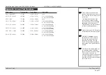
Appendix A: Lens Part Numbers
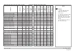
Throw ratios
Part number
Focus range
Lens shift
117-341
0.82 m - 2.71 m
none
115-339
1.02 m - 12.7 m
V: 0.5 (U) 0 (D) frame
H: 0.1 (L) 0.1 (R) frame
112-499
0.81 m - 5.08 m
none
112-500
1.33 m - 11.73 m
V: 0.5 (U) 0 (D) frame
H: 0.1 (L) 0.1 (R) frame
112-501
1.83 m - 14.9 m
V: 0.5 (U) 0 (D) frame
H: 0.1 (L) 0.1 (R) frame
112-502
2.36 m - 24.2 m
V: 0.5 (U) 0 (D) frame
H: 0.1 (L) 0.1 (R) frame
112-503
3.8 m - 35.35 m
V: 0.5 (U) 0 (D) frame
H: 0.1 (L) 0.1 (R) frame
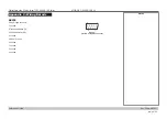
0.38 : 1 fixed (UST)
0.75 - 0.93 : 1 zoom*
0.76 : 1 fixed
1.25 - 1.79 : 1 zoom
1.7
3
- 2.27 : 1 zoom
2.22 - 3.67 : 1 zoom
3.58 - 5.38 : 1 zoom
5.31 - 8.26 : 1 zoom
112-504
5.59 m - 54.8 m
V: 0.5 (U) 0 (D) frame
H: 0.1 (L) 0.1 (R) frame
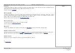
Notes
Throw distance calculations are
based on the distance from the outer
end of the lens, which will vary from
lens to lens.
The distance between the front
of the projector chassis and the
outer end of the lens is called
lens
extension
. Lens extensions is
measured when the lens is focused
at infinity, and fully extended.
Refer to the projector CAD drawings
for individual lens extension figures.
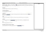
The
0.38 : 1 fixed lens
has no
adjustable shift value. However,
the lens has an inherent offset
depending on image size. See
the UST documentation published
separately on the Digital Projection
website.
The
0.75 - 0.93 : 1 zoom lens
has
an additional feature permitting
barrel correction for curved screens.
The front ring of the lens is a
manual control which provides focus
curvature adjustment to correct for
the different focal distances between
center and corner.

