3–4
Using the RRD42 Disc Drive
Tabletop
Components —
Rear
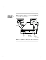
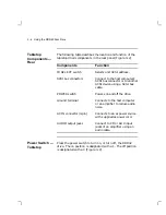
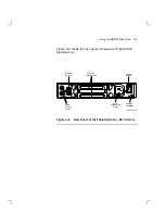
The following table describes the location and function of the
tabletop drive’s components in the rear panel (Figure 3–2).
Components
Function
ID SELECT switch
Selects unit SCSI address.
SCSI bus connectors
Connect to the host computer’s
SCSI bus connector or to another
SCSI device using a SCSI bus
cable.
POWER switch
Powers on and off the drive.
Ground terminal
Connects to the host computer
or an amplifier to reduce audio
noise.
AC IN connector (3-pin)
Connects to an ac power source
with supplied ac power cord.
AUDIO output jacks
Connect to CD or AUX input
jacks of an amplifier using an
audio cable.
Power Switch —
Tabletop
Press the power switch to turn on, or turn off, the RRD42
drive. The on position is designated with a 1. The off position
is designated with a 0 (Figure 3–2).
Summary of Contents for RRD42
Page 1: ...RRD42 Disc Drive Owner s Manual Order Number EK RRD42 OM 003 Digital Equipment Corporation...
Page 10: ......
Page 42: ......
Page 48: ......

