background image

System Care

________________________ WARNING __________________________

If you use a prepackaged screen cleaner, make sure that it is nonflammable.
Never spray the cleaner directly on the screen.  Instead, apply the cleaner to
a clean cloth, and then wipe the screen.

____________________________________________________________

Cleaning Your Mouse

If your mouse does not move smoothly or if the pointer jumps across the screen when you
are using the mouse, the ball inside the mouse might need cleaning.  To clean the ball,
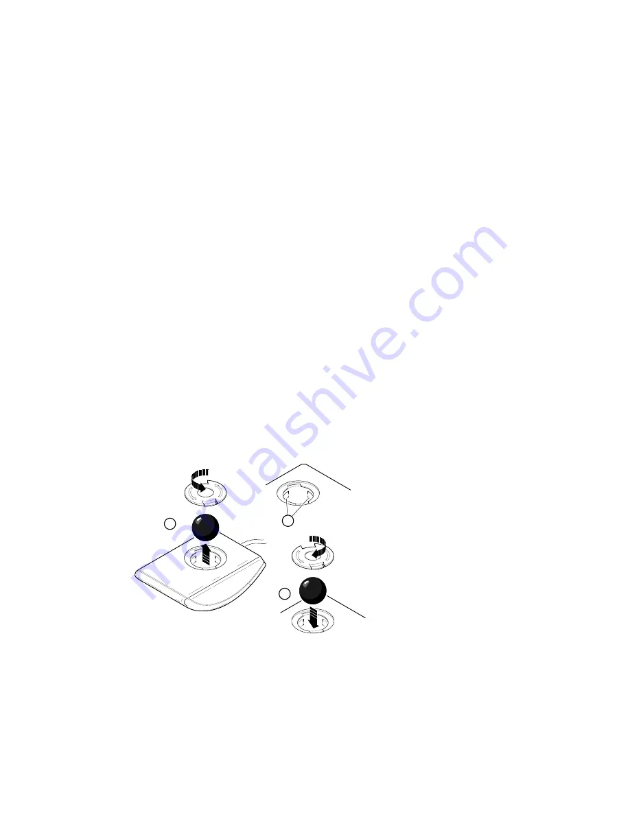
perform the following steps, as Figure B-1 shows:

1.

Turn the mouse over and remove the plate on the bottom.

2.

Remove the locking ring and the rubber ball 

.

3.

Clean the ball and rollers

‚ with a cotton swab that has been lightly dampened with a

mild detergent.

4.

Replace the ball and plate 

ƒ.


1

3

2

Figure B-1.  Cleaning the Mouse

Cleaning Your Keyboard

From time to time, your keyboard keys might get dirty with use.  Clean them with a fresh
cloth that has been lightly dampened with a mild detergent solution.

B-2

Summary of Contents for Digital AlphaStation 400 Series

Page 1: ...DigitalAlphaStation 400Series UserInformation Order Number EK PCDSA UI B01 Digital Equipment Corporation Maynard Massachusetts...

Page 2: ...stricted Rights Use duplication or disclosure by the U S Government is subject to restrictions as set forth in subparagraph c 1 ii of the Rights in Technical Data and Computer Software clause at DFARS...

Page 3: ...e instructions may cause harmful interference to radio communications However there is no guarantee that interference will not occur in a particular installation If this equipment does cause harmful i...

Page 4: ......

Page 5: ...ting Your System 1 2 Posture and Work Habits 1 2 Identifying the Correct AC Power Cord 1 5 Installing Your System 1 6 Connecting System Parts 1 7 Network Connection 1 9 Starting Your System 1 9 Preloa...

Page 6: ...urations 3 6 Adding Memory Modules 3 7 Installing Expansion Boards 3 8 Adding Mass Storage Devices 3 10 Expansion Brackets 3 10 SCSI Bus Length 3 10 SCSI Addresses 3 10 SCSI Termination 3 11 Internal...

Page 7: ...o OpenVMS or OSF Console A 4 SRM Console A 5 SRM Console Conventions A 5 SRM Console Special Characters A 6 Boot Command A 7 Boot Command Examples A 8 Set Command A 9 Set Command Examples A 9 Show Com...

Page 8: ...s C 6 Power Supply and Input Power Requirements C 6 Motherboard Jumpers C 6 D Device Mapping Introduction D 1 I O Address Map D 1 Interrupt Map D 2 DMA Channel Assignments D 3 E Updating System Firmwa...

Page 9: ...stalling an Expansion Board 3 9 3 7 Removing Plastic Filler Panel from the Upper Drive Bay 3 12 3 8 Removing the Metal Plate 3 13 3 9 Exchange Bracket Mounting 3 13 3 10 Inserting a Device into the Up...

Page 10: ...1 Computer Performance Specifications C 1 C 2 Computer Dimensions C 2 C 3 Computer Environmental Specifications C 2 C 4 Acoustics Declared Values per ISO 9296 and ISO 7779 C 2 C 5 Bidirectional Parall...

Page 11: ...n here to start use update troubleshoot and configure your Digital AlphaStation 400 Series system You also can find general system information such as console commands and system care here Audience If...

Page 12: ...itor and mouse Appendix C Technical Specifications Appendix D Device Mapping I O addresses and interrupts Appendix E Updating System Firmware Appendix F Starting an Operating System Installation Appen...

Page 13: ...File allocation table FDC Floppy disk controller flashROM Electrically erasable rewriteable nonvolatile memory GB A GB suffix to a numerical value indicates size in gigabytes for example 1 GB A gigab...

Page 14: ...xample 550 MB A megabyte equals 1 048 576 bytes MHz Megahertz ns Nanoseconds NVRAM Nonvolatile random access memory OSF DEC OSF 1 operating system PCI Peripheral component interconnect RAID Redundant...

Page 15: ...s the presence of a hazard that can cause damage to hardware or that might corrupt software ____________________________________________________________ __________________________ NOTE _______________...

Page 16: ...number EK PCDSA II presents a graphical overview of the Digital AlphaStation 400 Series installation Digital AlphaStation 200 400 Series Technical Information order number EK PCDSA TI This optional ma...

Page 17: ...on as a client in an office network environment This chapter describes how to start install restart and turn off your Digital AlphaStation 400 Series system You can also find information here about pr...

Page 18: ...e has been installed Carefully review the software license agreement shipped with your system ____________________________________________________________ ________________________WARNING _____________...

Page 19: ...he seat so you do not compress the area behind them which could restrict the blood flow 4 Your upper body is erect and your lower back is supported with a backrest Keyboard and Mouse 5 Your wrists are...

Page 20: ...or to the side of your work area and distribute the lighting evenly on your work area Noise Keep background noise at a minimum Background noise above 65 dBA is tiring Sound absorbing materials for exa...

Page 21: ...0V AC input power Modifying the power cord can cause personal injury and severe equipment damage ____________________________________________________________ Power cords supplied with the Digital Alph...

Page 22: ...front and out of the rear of the system unit 2 The system is designed to be installed vertically Do not use a stand or rack that would hold the system on its side _____________________________________...

Page 23: ...or 230 V as Figure 1 4 shows 1 2 MLO 012768 115 230 Figure 1 4 Voltage Selector Switch ________________________ CAUTION __________________________ Improper voltage selection can damage the system s po...

Page 24: ...Amps at 115 Volts 1 Amp at 230 Volts Plug higher amperage video monitors into a wall receptacle ____________________________________________________________ 1 2 MLO 012664 Figure 1 5 Connecting Cable...

Page 25: ...e location of the system unit power button MLO 012665 Figure 1 6 Starting Your System 2 If necessary adjust the monitor contrast and brightness to obtain a readable screen display Refer to the informa...

Page 26: ...s Microsoft Windows NT Workstation If you ordered a system with the Microsoft Windows NT Workstation operating system you will see the following display after power on and initialization ARC Multiboot...

Page 27: ...ystems follow these steps from the Boot menu 1 Select Supplementary menu 2 Select Set up the system 3 Select Switch to OpenVMS or OSF console 4 Select Switch to OpenVMS or Select Switch to OSF 5 Selec...

Page 28: ...with the appropriate command from the table below Operating System Action Microsoft Windows NT Workstation From the Program Manager File Menu choose Shutdown Choose the OK button to confirm DEC OSF 1...

Page 29: ...ft of internal components your Digital AlphaStation 400 Series system comes with a chassis key lock which is located on the back of your system box When this lock is in the locked position no one else...

Page 30: ......

Page 31: ...formation The system box has the following features Three storage bays for half height 5 25 inch devices Floppy disk controller that supports two floppy drives or one floppy and one tape drive SCSI 2...

Page 32: ...ultiple bus masters 32 bit data transfer at 132 MB megabytes per second peak PCI to ISA bridge capability that allows you to use commonly available ISA options SCSI Controller The Digital AlphaStation...

Page 33: ...etermined by the installed application software 4 Indicator lights Indicates whether the NumLock CapsLock or ScrollLock has been activated 5 Numeric keypad These keys perform numeric functions and sof...

Page 34: ...ts System Front View Figure 2 2 is a front view of the system showing the location of the controls and indicators Table 2 2 describes these items MLO 012666 1 2 3 7 6 5 4 Figure 2 2 Front Controls and...

Page 35: ...5 Power On Off button Turns AC power on and off 6 Halt Reset button When set to Halt this button is operating system specific See your operating system documentation When set to Reset default this bu...

Page 36: ...nts System Rear View Figure 2 3 shows the rear connectors and lock Table 2 3 lists the rear connectors and lock and describes their functions 1 2 MLO 012667 1 2 3 4 5 6 7 8 9 10 12 11 Figure 2 3 Rear...

Page 37: ...a 101 or 102 key keyboard 6 Serial port connectors Connects serial devices 7 SCSI connector Provides the interface between the system unit and external SCSI devices 8 Parallel port connector Allows yo...

Page 38: ......

Page 39: ...connected and video cable 3 Wait at least 20 seconds to allow time for the power supply capacitors to safely discharge 4 Unlock the side panels To unlock the side panels turn the key clockwise to a h...

Page 40: ...___________________ If you are installing or removing drives you must remove both side panels Otherwise remove only the left side panel ____________________________________________________________ MLO...

Page 41: ...ystem unit components MLO 012669 7 6 5 4 3 2 1 Figure 3 2 System Unit Components Table 3 1 System Unit Components Figure Legend Component 1 Power supply 2 Two PCI three ISA and one combination PCI ISA...

Page 42: ...our System Motherboard Figure 3 3 shows the location of the motherboard components Table 3 2 lists the motherboard components 1 2 3 4 5 6 12 7 MLO 012668 8 9 10 11 13 14 15 Figure 3 3 Motherboard Comp...

Page 43: ...n slot 3 PCI expansion slots 4 External SCSI connector and bidirectional parallel port 5 Power connector 3 3 V 6 Serial ports 7 Mouse and keyboard connectors 8 FDC connector 9 Internal SCSI connector...

Page 44: ...are pairs of single in line memory modules SIMMs a 16 MB option consisting of two 8 MB SIMMs a 32 MB option consisting of two 16 MB SIMMs or a 64 MB option consisting of two 32 MB SIMMs SIMMs are alwa...

Page 45: ...eft side panel 3 Install the SIMM into the socket at a 45 degree angle Figure 3 5 Be sure that the notch is oriented as shown Rock the SIMM gently until it is seated evenly into the bottom of the sock...

Page 46: ...base F For further information on IRQs refer to the ISACFG command in Appendix A ____________________________________________________________ F Refer to your option module documentation for instructio...

Page 47: ...he back of the system unit Connect any external devices and plug the power cord into the wall outlet 8 For ISA options added to DEC OSF 1 or OpenVMS systems run the configuration utility ISACFG from t...

Page 48: ...all half height devices in any of the three positions in the upper drive bay area To install a 3 5 inch device in the upper drive bay install the drive expansion brackets onto the device _____________...

Page 49: ...appropriate drive manual to disable the new peripheral s termination External Termination When no external peripherals are present use the console firmware to terminate the external portion of the SC...

Page 50: ...rewdriver inserted through one of the screw holes in the side of the drive bay MLO 012672 Figure 3 7 Removing Plastic Filler Panel from the Upper Drive Bay 3 Refer to your drive documentation to confi...

Page 51: ...893 Figure 3 8 Removing the Metal Plate 5 If you are installing a 3 5 inch device add the 3 5 to 5 25 inch exchange brackets as Figure 3 9 shows Fasten the drive with the screws provided Figure 3 9 Ex...

Page 52: ...If you have a SCSI tape drive it will connect to the SCSI cable If you have an FDC tape drive it will connect to the FDC cable the same cable used by the floppy diskette drive Be sure that the cable i...

Page 53: ...Expanding Your System Figure 3 11 SCSI and FDC Cable Configuration 3 15...

Page 54: ...supply MLO 012679 Figure 3 12 Power Cable Configuration 10 Replace the metal plate that you removed in step 4 11 Replace and lock the side panels 12 Connect the power cord and monitor cord to the bac...

Page 55: ...ord from the wall outlet Unplug the power and monitor cords from the back of the system unit 2 Unlock and remove the left side panel as described earlier 3 Remove the cables from the devices in the lo...

Page 56: ...Expanding Your System MLO 012675 Figure 3 13 Removing the Lower Drive Bay Assembly 3 18...

Page 57: ...___________________________________ 7 Replace the lower drive assembly in the system by sliding it forward until the retaining clip latches 8 Reconnect the data and power cables to the drives ________...

Page 58: ......

Page 59: ...o check the monitor keyboard and mouse cables to ensure that they are connected and seated properly 3 Press the Halt Reset button If your system fails to boot turn it off wait 20 seconds and then turn...

Page 60: ...ot on System is not plugged in No power at the wall outlet Power supply failure Internal power supply cables not reconnected after installing options Turn off the system plug it in and then turn it ba...

Page 61: ...endix A Console Commands Use gathered information to identify target devices for boot command and verify that the system sees all installed devices Windows NT Use the ARC console to display the availa...

Page 62: ...ariables Refer to Appendix A Console Commands Format the hard disk drive or correctly partition the hard disk drive using the supplied software Install software on the requested partition Target boot...

Page 63: ...o the keyboard port 1 Connect the keyboard to the keyboard port 1 No response to mouse commands Mouse is not connected Mouse is connected to the keyboard port Mouse driver not installed Mouse ball sti...

Page 64: ...floppy Use a floppy of the proper density for your drive Try another floppy Slide the write protect switch so that the hole is not visible Insert a floppy Table 4 3 Monitor Troubleshooting Problem Po...

Page 65: ...uld not find 2 MB of good memory or 2 there was no memory available 3 2 1 The DROM code was unable to read the header of the flashROM or the flashROM checksum failed Therefore the DROM code attempted...

Page 66: ...l l DC NVRAM nonvolatile random access memory test failed l l l l l l DB SCSI controller test failed l l l l l DA PCI peripheral component interconnect ISA industry standard architecture bridge test f...

Page 67: ...NT Workstation operating system The ARC console uses a menu interface When a Digital AlphaStation 400 Series system is powered on initialization is performed During initialization the firmware checks...

Page 68: ...number SCSI ID of the drive and the partition number Set Default Configuration The Set default configuration command is located in the Setup menu Use this command to select Monitor resolution Floppy d...

Page 69: ...alternate operating system command is located in the Boot menu Use this command to select a boot selection identifier that is different from the default selection For example you can have multiple ver...

Page 70: ...enu You must put the Microsoft Windows NT Workstation CD compact disc into the CD drive before selecting this command Switch to OpenVMS or OSF Console The Switch to OpenVMS or OSF console command is l...

Page 71: ...mine deposit ISACFG SRM Console Conventions Table A 1 lists SRM console conventions Table A 1 SRM Console Conventions Item Convention Console prompt Continuation line prompt _ Maximum command length 2...

Page 72: ...lt Ctrl B or Recalls previous commands The last 16 commands are stored Ctrl C Terminates the foreground process Ctrl D or Moves the cursor left one position Ctrl E Moves the cursor to the end of the l...

Page 73: ...ault boot file flags longword longword Specifies additional information for the operating system For systems with OpenVMS root number and boot flags are specified here For DEC OSF 1 systems the follow...

Page 74: ...ult boot device boot ewa0 Boots the system from Ethernet port ewa0 boot file dec2 sys mke0 Boots the file named dec2 sys from Ethernet port mke0 boot protocol bootp eza0 Boots using TCP IP BOOTP proto...

Page 75: ...ither a numeric value or an ASCII string default Restores an environment variable to its default value integer Creates an environment variable as an integer string Creates an environment variable as a...

Page 76: ...on Description config Displays the current memory configuration PCI logical slots and ISA logical slots based on ISACFG utility input to the configuration database device device name Displays the devi...

Page 77: ...information such as system designation drive model or Ethernet address show memory 48 Meg of System Memory Bank 0 16 Mbytes 8 MB per Simm Starting at 0x2000000 Bank 1 32 Mbytes 16 MB per Simm Starting...

Page 78: ...aword of data h Hexaword of data d Displays data as a decoded macro instruction physical References physical address space virtual References virtual address space gpr References general purpose regis...

Page 79: ...00002 Examines R0 using address space e gpr 0 gpr 0 R0 0000000000000002 Examines R0 using device name e pc PC psr 0 PC FFFFFFFF80072954 Examines the system examine n 5 r7 gpr 38 R7 0000000000000000 gp...

Page 80: ...ta o Octaword of data h Hexaword of data physical References physical address space virtual References virtual address space gpr References general purpose register address space fpr References floati...

Page 81: ...mmediately preceding the last location referenced by an examine or deposit The location last referenced by an examine or deposit The location addressed by the last location referenced by an examine or...

Page 82: ...or device list from which the system attempts to boot If the system software is preloaded the variable is preset to point to the device containing the preloaded software Otherwise the default value i...

Page 83: ...CSI controller is assigned automatically to IRQ11 For example if your system has two PCI slots occupied you can add up to three ISA devices You can add a fourth ISA device if ISACFG is used to disable...

Page 84: ...or a particular device entry irq 0 3 Allows you to assign up to four IRQ interrupt request channels to the device use decimal IRQ levels membase 0 2 Specifies up to three R W ISA memory regions memlen...

Page 85: ...tion guide and release notes The operating system is prepared for the ISA option 2 Shut down the system The system is at the console prompt 3 isacfg options Adds the new ISA option to the SRM console...

Page 86: ...nes for clarity when entering a command type it on one line F Refer to the equipment logs in Appendix G for tables you can use to record system configuration data Adding the DE205 option add_de205 or...

Page 87: ...ing do not allow any excess fluid to leak into the system keyboard or monitor Wait until the system is completely dry before applying power ____________________________________________________________...

Page 88: ...oss the screen when you are using the mouse the ball inside the mouse might need cleaning To clean the ball perform the following steps as Figure B 1 shows 1 Turn the mouse over and remove the plate o...

Page 89: ...he next section Packing Your System Packing Your System If you are moving the system a short distance for example from one room to another in the same building you do not have to pack it If you are sh...

Page 90: ......

Page 91: ...nt requirements Motherboard jumpers System Specifications Tables C 1 through C 4 list the Digital AlphaStation 400 Series system processor features dimensions environmental and acoustics specification...

Page 92: ...ng 10 to 90 relative humidity maximum wet bulb 65 C 149 F Altitude Operating Nonoperating 2 438 m 8 000 ft maximum 4 876 m 16 000 ft maximum Shipping vibration IAW Federal Standard 101 method 5019 Non...

Page 93: ...or other parallel devices Table C 5 lists pin assignments An asterisk after a signal name indicates an active low signal Table C 5 Bidirectional Parallel Port Pinouts DB25 Pin Signal Function 1 STB R...

Page 94: ...inouts DB9 Pin Signal Function 1 DCD Data carrier detect 2 RXD Receive data 3 TXD Transmit data 4 DTR Data terminal ready 5 GND Ground 6 DSR Data set ready 7 RTS Request to send 8 CTS Clear to send 9...

Page 95: ...Signal 1 gnd 26 DB 0 2 gnd 27 DB 1 3 gnd 28 DB 2 4 gnd 29 DB 3 5 gnd 30 DB 4 6 gnd 31 DB 5 7 gnd 32 DB 6 8 gnd 33 DB 7 9 gnd 34 DB P 10 gnd 35 gnd 11 gnd 36 gnd 12 reserved 37 reserved 13 open 38 TER...

Page 96: ...equency Range 100 V AC 120 V AC 88 V AC 132 V AC 8 A 47 Hz 63 Hz 220 V AC 240 V AC 176 V AC 264 V AC 4 A 47 Hz 63 Hz 1 Includes outlet current Motherboard Jumpers Jumper pins allow you to set specific...

Page 97: ...are safely grounded Wear a grounded wrist strap or touch an exposed metal part of the system unit chassis A static discharge from your fingers can permanently damage electronic components ___________...

Page 98: ...use J32 1 to 2 J32 2 only D J33 For service use J33 1 to 2 J33 2 only D J34 Recovery mode J34 1 to 2 Recovery mode J34 2 only D Normal J35 BIOS upgrade J35 1 to 2 D Enabled J35 2 only Disabled J39 CPU...

Page 99: ...upt assignments DMA channel assignments I O Address Map Table D 1 presents information on the I O address map Table D 1 I O Address Map ISA I O Addresses Devices 0000 02F7 Reserved 02F8 02FF Serial po...

Page 100: ...ndows NT operating system or by the SRM console as in the OpenVMS and DEC OSF 1 operating systems Table D 2 System Interrupt Assignments IRQ Source 0 Timer counter 1 Keyboard 2 Internal cascade of 825...

Page 101: ...A channel conflicts by not assigning multiple devices to the same channel Table D 3 DMA Channel Assignments Channel Device 0 Available to ISA slots 1 Available to ISA slots 2 Floppy disk controller 3...

Page 102: ......

Page 103: ...nce manual console firmware for the DEC OSF 1 and OpenVMS operating systems Update Utility Use the update utility to update your ARC and SRM firmware The update utility contains three images Update ut...

Page 104: ...are type update The following information is displayed as the firmware is being updated The actual information might change between versions Apu update Version 3 0 f Vendor DEC Product Digital AlphaSt...

Page 105: ...1 Manufacturer Amd 0x01 28F020 0x2a 256K x 8 APU I ROM SET NOT ERASED APU I PRECHARGING DEVICE 0x80000 APU I ERASING ROM DEVICE 0x80000 APU I PROGRAMMING DEVICE 0x60e40 APU I ROM 0 VERIFYING ROM IMAGE...

Page 106: ...4 Use the verify SRM command to verify the integrity of the SRM firmware Apu ver srm Version bl3_1 Vendor DEC Product Digital AlphaStation 400 Series Firmware SRM Length 0x62a00 Rom Set 0 Roms 0 1 APU...

Page 107: ...OSF 1 F 3 Install OpenVMS F 4 ________________________ CAUTION __________________________ If you boot from a DEC OSF 1 or OpenVMS disk and also occasionally boot Microsoft Windows NT Workstation from...

Page 108: ...s 6 MB formatted FAT and identified as the system partition Refer to Table F 1 for the steps to start installing Windows NT Workstation on a properly partitioned and formatted disk Table F 1 Starting...

Page 109: ...ROM into the CD drive CD ROM drive is ready 3 From the ARC console select Run a Program You are prompted for the program name ARCINST the ARC installation program provides a means to partition and fo...

Page 110: ...n and press return Partition formatted successfully 11 Press any key to continue Configure Partitions menu reappears 12 Choose Create Partition A list of available target devices appears 13 Select the...

Page 111: ...nds Cycling power after selecting the OpenVMS or OSF 1 console results in the system s restarting with the SRM console running 3 At the SRM prompt type set boot_osflags Clear the boot_osflags variable...

Page 112: ...uses the system to run the SRM console after the next power cycle 2 Cycle the system s power Leave the system off for 20 seconds Cycling power after selecting the OpenVMS or OSF 1 console results in t...

Page 113: ...he Equipment Log when you add options Equipment Log The log consists of six tables which you can use to record the following information Your system s hardware components Table G 1 Your system s ISA e...

Page 114: ...storage device 4 Use Table G 2 to keep track of your AlphaStation 400 Series system s expansion options The upper portion of the table shows the standard devices You can use the lower portion of the t...

Page 115: ...and Memlen DMAmode and chan IRQ 0 3 Keyboard KBD 0 60 1 Mouse MOUSE 0 60 12 Serial Line 1 COM1 0 3F8 4 Serial Line 2 COM2 0 2F8 3 Parallel port LPT1 0 3BC 7 FDC FLOPPY 0 3F0 2 6 Motherboard ISA Expans...

Page 116: ...System Specifics CPU speed and model Firmware version Memory size Video module Table G 5 Installed Software Operating System or Application Software Version Number License Number Date Installed Table...

Page 117: ...troubleshooting 4 1 autobooting A 3 moving B 3 boot command A 3 packing B 3 boot menu A 1 security 1 13 boot selection menu A 2 side panels 3 1 booting an alternate operating system A 3 specification...

Page 118: ...nitial troubleshooting 4 1 control_scsi_term 3 11 A 16 input power requirements C 6 modifying A 9 Install os_type A 16 lower bay device 3 17 pci_parity A 16 mass storage devices 3 10 setting A 9 optio...

Page 119: ...mory auxiliary jack banks 3 6 current limit 1 8 configurations 3 6 cabling 3 16 installing 3 6 cord Monitor adjustments 1 9 specifications 1 5 Motherboard switch 1 7 1 9 2 5 components 3 4 Precautions...

Page 120: ...1 9 cooling 1 6 troubleshooting 4 1 ergonomics 1 2 T Software license notice label 1 2 Termination Specifications SCSI 3 11 acoustic C 2 Troubleshooting computer C 1 boot device not listed 4 4 compute...

Page 121: ...Index V Ventilation 1 6 Voltage selector switch 1 7 2 7 W Windows NT 1 10 arcinst F 3 creating partitions F 3 partitioning the disk F 3 shutdown 1 12 starting an install F 2 Index 5...

Reviews: