


DVM-500Ultra Installation Guide REV B
Page 7
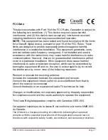
SYSTEM
DIAGRAM
GPS Antenna
Front Camera
WIFI USB Dongle
Interface Box
Monitor
Wireless Transfer
Module (optional)
USB1
USB2
Serial
WTM
POWER
HARNESS
RED = Constant 12V+
WHITE = Switched 12V+
BLACK = Ground
(See WTM-555
installation guide)
Constant 12V+ Ground
Switched
Ignition 12V+
Input Triggers
(see page 13)
Vehicle to IF Box Harness
DVM to I/O Box harness
Shown With Optional
Wireless Transfer Module
(WTM)
Voice Vault Wireless Microphone and Charger
Assembly with Cigarette Lighter Adapter
DVM Y Cable
WTM to DVM serial cable
Monitor and Camera
Connections
Controller (optional)
USB
Cable
Monitor Cable
Fuse


