


Get started with the XBee Smart Modem Development Kit
Interface with the XBIB-C-GPS module
Digi XBee3 Cellular LTE-M/NB-IoT Global Smart Modem User Guide
27
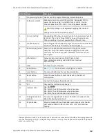
Number Item
Description
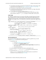
1
40-pin
header
This header is used to connect the XBIB-C-GPS board to a compatible XBIB
development board. Insert the XBIB-C-GPS module slowly with alternating
pressure on the upper and lower parts of the connector. If added or removed
improperly, the pins on the attached board could bend out of shape.
2
GPS
unit
This is the CAM-M8Q-0-10 module made by u-blox. This is what makes the GPS
measurements. Proper orientation is with the board laying completely flat, with
the module facing towards the sky.
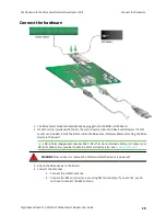
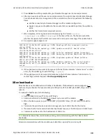
Interface with the XBIB-C-GPS module
The XBee Smart Modem can interface with the XBIB-C-GPS board through the large 40-pin header.
This header is designed to fit into XBIB-C development board. This allows the XBee Smart Modem in
the XBIB-C board to communicate with the XBIB-C-GPS board—provided the XBee device used has
MicroPython capabilities (see
to determine which devices have MicroPython capabilities).
There are two ways to interface with the XBIB-C-GPS board: through the host board’s Secondary
UART or through the I2C compliant lines.
The following picture shows a typical setup:


