background image

Transport WR Series Installation Guide 


1  Introduction 

Transport WR series routers are compact IP routers that facilitate the transmission of data 
over 

different types of “cellular” networks depending on the model. 

The routers can be configured either by using commands entered at the serial port (much 
like  a  modem),  or  via  the  built-in  Web  interface.  We  recommend  that  you  use  the  Web 
interface whenever possible. 

In addition to many standard LAN and Internet protocols such as PPP, the  Transport WR 
series  products  provide  a  combination  of  powerful  but  easy  to  use  configuration, 
management and diagnostic tools. This makes them simple and cost-effective solutions for 
migrating  existing  terminal  or  telemetry  equipment,  which  use  wired  networks  (PSTN, 
ISDN, etc.), to wireless operation.  

1.1 

Front Panel Features 

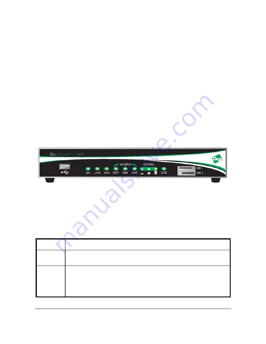
The front panel of the unit incorporates the USB host connector, 10 LED indicators and the 
two SIM card-holders as shown in the following illustration: 


USB Host Connector 

The USB host connector may be used to connect compatible USB 2.0 client devices such 
as memory sticks, serial adapters, etc. Note that the total current available to power USB 
devices is 0.5A.  

Status Indicators 

The status indicators operate as follows: 

ON 

Illuminates steady when power is applied. 

LAN 

Illuminates  steady  when  there  is  a  network  connection  to  the  LAN  port 
and flashes when data is transmitted or received. 

WN 

The  indicator  labelled  WN  (Wireless  Network)  flashes  to  show  which 
network mode the router is operating in as follows: 

Off 

– no service 

1 blink 

– GPRS mode 

Summary of Contents for Digi TransPort WR

Page 1: ...T T r r a a n n s s p p o o r r t t W W R R Cellular Routers Wireless WAN router switch Installation Guide ...

Page 2: ... disposal instructions The WEEE Waste Electrical and Electronic Equipment 2002 96 EC directive has been introduced to ensure that electrical electronic products are recycled using the best available recovery techniques to minimize the impact on the environment This product contains high quality materials and components which can be recycled At the end of its life this product MUST NOT be mixed wit...

Page 3: ...he unit contains no electronic components that can be serviced or replaced by the user Any attempt to service or repair the unit by the user will void the product warranty 5 Products in the Transport WR family are designed for indoor use only and should be used in an environment that is suitable for computers and other electronic equipment 6 Ports that are capable of connecting to other apparatus ...

Page 4: ...doubt about potential danger contact the physician or the manufacturer of the device to verify that the equipment is properly shielded Pacemaker patients are advised to keep the wireless router away from the pacemaker while it is on Wireless routers must NOT be operated on aircraft The operation of wireless appliances in an aircraft is forbidden to prevent interference with communications systems ...

Page 5: ...J45 connector 1 x USB 2 0 host port 2 x SIM sockets GSM models 1 x Wireless WAN interface varies with model All models may also be purchased with one of a number of hardware options which are listed in the section entitled Optional Features below Package Contents When you receive the router carefully unpack it and check the contents These should include Item System Unit 5V DC 3A power supply Insta...

Page 6: ...ating existing terminal or telemetry equipment which use wired networks PSTN ISDN etc to wireless operation 1 1 Front Panel Features The front panel of the unit incorporates the USB host connector 10 LED indicators and the two SIM card holders as shown in the following illustration USB Host Connector The USB host connector may be used to connect compatible USB 2 0 client devices such as memory sti...

Page 7: ...ength as follows None illuminated 113 dBm effectively no signal 1 LED illuminated 112 dBm and 87 dBm weak 2 LED s illuminated 86 dBm and 71 dBm medium 3 LED s illuminated 70 dBm and 51 dBm strong DTE Illuminates steady if a terminal is connected to the ASY0 serial port and the DTR signal is on Flashes when data is transmitted or received SIM Sockets On the Transport WR41 E H and U the two sockets ...

Page 8: ...ceiver supports diversity antenna capability to improve performance and are there supplied with two stub antennas One of these should be fitted to this connector and the other to the ANT AUX connector Note Stub antennas are provided as standard but a range of suitable alternative for use in different applications may be purchased separately W WAN ANT AUX This SMA connector is used on the Transport...

Page 9: ...eatures Routers are available with a variety of hardware options including 1 x ASY Provides an additional asynchronous serial port using a 25 way D connector 3 x ASY Provides three additional asynchronous serial ports using RJ45 connectors 1 x SYN Provides an X 21 RS422 RS232 synchronous serial port using a 25 way D connector 1 x GPS Provides GPS geo location capability 1 x ISDN BRI Provides an IS...

Page 10: ...ut in some circumstances it may be necessary to use a window mounted or magnetically mounted antenna with an extended cable to allow the antenna itself to be positioned to provide the best possible signal reception Digi International can supply a range of suitable antennas Step 1 Installing the SIM card GSM models only The router incorporates two separate SIM card holders so that if your applicati...

Page 11: ...ntennas supplied as standard e g two wall mount antennas the separation between the two should be no less than the separation between the two associated connectors on the rear panel of the unit Step 3 Connecting the LAN cable Plug one end of one of the supplied Ethernet cable into the RJ45 socket labelled LAN 0 Plug the other end into the LAN socket on your PC or notebook Step 4 Connecting the ser...

Page 12: ...s to one on the same subnet 192 168 1 will enable you to connect to the unit s Web interface Step 1 Connect to the Web Interface Open a browser and connect to the Web interface by connecting to http 192 168 1 1 It is recommended to change the default username and password on the device Default Username username Default Password password This setting can be changed by going to Configuration Securit...

Page 13: ...PPP username and password they you can skip this next step Configuration Interfaces PPP PPP 0 4 PPP 1 Standard Enter the PPP username password and confirm password Click OK Follow prompts to save the configuration to flash memory Transport WR41 C CDMA Devices Start the CDMA Provisioning by going to Configuration Interfaces Mobile W WAN Module CDMA Provisioning ...

Page 14: ...s Diagnostics Event Log Step 4 Test Mobile Connection Depending on the wireless plan being used you should be able to perform a test to a remote host or browse the Internet By default the Digi Transport should have issued your workstation an IP address of 192 168 1 100 via DHCP DHCP will pass the proper default gateway and DNS server information Verify this on the workstation by using the ipconfig...

Page 15: ...r greater description on all the features and settings available on the device there is a comprehensive Reference Guide available on the Digi Support website www digi com Advanced Configuration VPN Configuration VPN Routing Configuration Routing Firewall Configuration Security Firewall Users Configuration Security Users Alarms Configuration Alarms VRRP Configuration Interfaces Eth x Configure Seri...

Page 16: ...link MO 0201 850 1900 2100 Rx diversity MHz Quad band GSM 850 900 1800 1900 MHz EDGE E GPRS multi slot class 12 max 236 8 kbps downlink mobile station class B modulation and coding scheme MCS1 9 GPRS multi slot class 12 mobile station class B PBCCH support coding schemes CS 1 4 WR41 U GSM GPRS EDGE UMTS HSDPA HSUPA modem HSUPA mode 2 Mbps Category 5 HSDPA 1 8 Categories 1 4 11 and 12 HSDPA 3 6 Cat...

Page 17: ... IS 856 A Forward link up to 31 Mbps Reverse link 1 8 Mbps 1 x EV DO Revision O IS 85L Forward link up to 2 4 Mbps Reverse link 153 6 Kbps 1 x RTT IS 2000 Forward and reverse link speeds up to 153 6 Kbps USB ports One USB 2 0 Full speed Host 12 Mbits second maximum throughput Ethernet interface 10 100Base T auto sensing auto MDI MDX RJ45 Serial interface Asynchronous RS232 compatible RJ45 ...

Reviews: