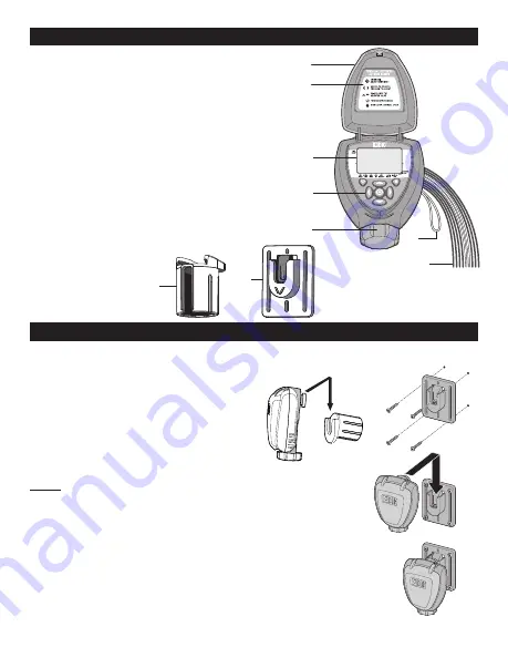
2. COMPONENT IDENTIFICATION
1. Controller cover (lid)
2. Quick programming reference label
3. LCD display with icon-based navigation
4. 5 button programming keypad
5. Battery compartment cap for two AA
alkaline batteries (AA batteries not included)
6. Yellow wire connection for rain sensor
7. Two, four or six 18” red solenoid wires,
two 18” white common wires, and one
18” black master valve wire
8. Solenoid mounting sleeve
9. Wall/valve box
mounting plate
3.
VALVE OR WALL MOUNTING
.
The controller can be mounted directly on top of any of the valves installed or mounted into
the valve box.
3.1 VALVE MOUNTING:
1. Slide the controller mounting boss
q
into the solenoid sleeve
w
to secure
and set it in the desired position on top
of the solenoid (Figure A).
NOTE:
After mounting the sleeve to the solenoid, turning the solenoid
sleeve counter clockwise will turn the valve on, and turning the
solenoid sleeve clockwise will turn it off.
3.2 WALL MOUNTING:
1. Place the mounting plate
e
on the wall and secure using 4
screws (not included).
2. Slide the controller mounting boss
r
into the mounting
plate to secure (Figure B).
i
o
PROGRAM
VALVE #
2
r
r
y
t
q
q
u
e
e
w
w
Figure B
Figure A


