


5750-212
Revision A
Page 39
5 Press J on the QWERTY keypad. The LCD will prompt for the number of the dot that is not printing like
the other dots. The top dot on the printhead is dot number 1 and the bottom dot is dot number 7.
6 Scroll to the number of the problem dot.
7 Press ENTER.
8 The LCD will prompt for a new diameter of the selected dot. Move to the second digit (250) and scroll
to a new value. The scroll changes by units of 10.
9 Press SET-UP. The LCD will ask if you want to keep the "Factory Setting Y/N?" Select "1-NO." When you
select NO, the I.V./700 remembers the new dot diameter value only until the next initialization.
By running print samples and altering the diameter of a single dot, you can make that single dot match
the appearance of the other dots.
10 When you achieve the best print, select "2-YES" when exiting this function. This choice makes the new
pulse width value permanent.
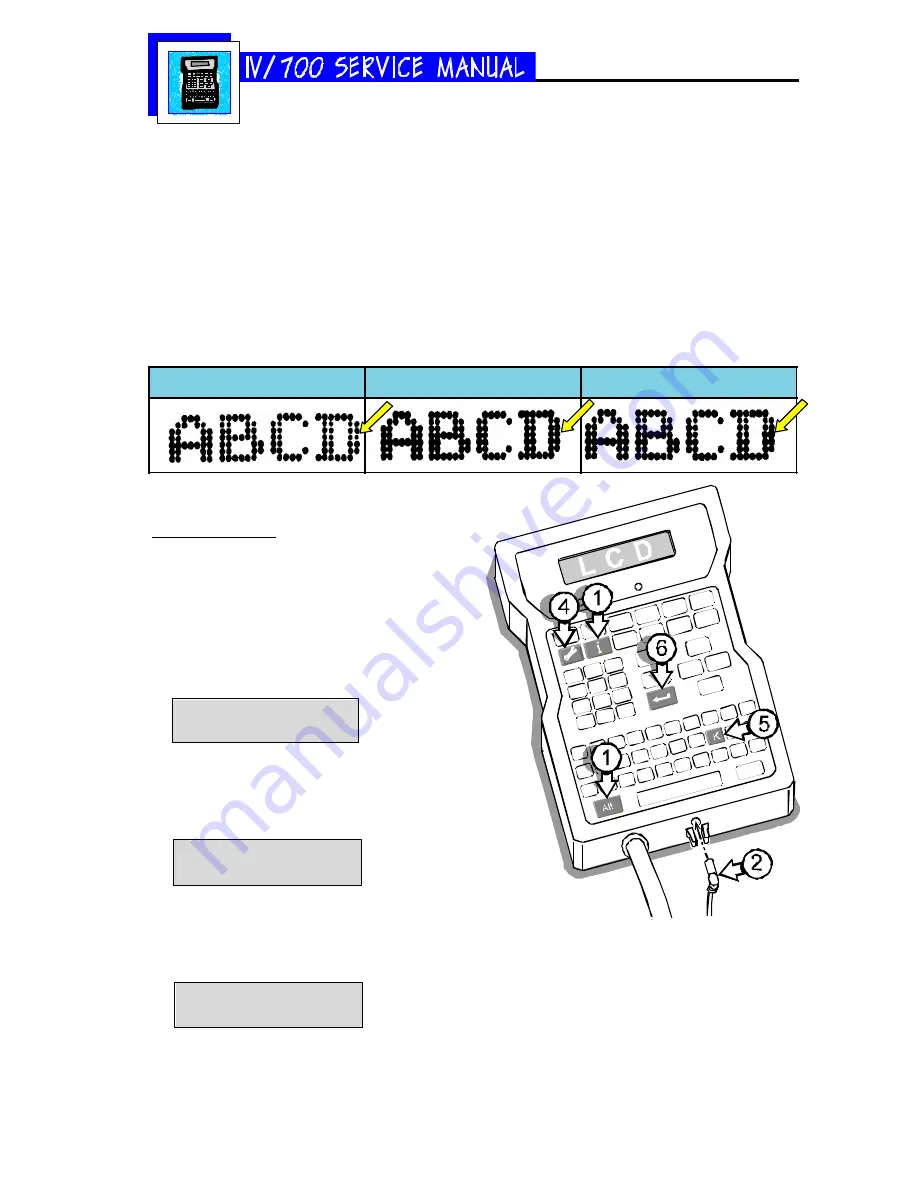
Small Dot #4
Dot #4 adjusted correctly
Dot #4 oversized
After sitting idle for several minutes, the
initial prints have dots that are too small.
First Dot Adjustment
This procedure allows you to overcome this problem
by independently increasing dot sizes exclusively on
the first print. Second and all subsequent prints return
to their defined dot-size settings.
1 Press and hold ALT+INFORMATION.
2 Plug in the barrel connector.
3 Release the keys when the LCD shows "Informa-
tion."
Information
1-Unused Messages
4 Press SET-UP
5 Press K on the QWERTY keypad. The LCD will
prompt for the time in seconds that the printer
will stand idle."
1st dot time:000 sec
6 Type in the amount of time and press ENTER.
7 The LCD will show "1st Dot Adjust:1" for the
first valve (dot) at the top of the printhead. Press
ENTER.
1st dot adjust:1
Dot Adjustment:30
Summary of Contents for I.V./700
Page 4: ...5750 212 Revision A Page 4 I V 700 Components...
Page 26: ...5750 212 Revision A Page 26 Hardware Block Diagram HBD1...
Page 30: ...5750 212 Revision A Page 30 Modular Parts Kits...
Page 31: ...5750 212 Revision A Page 31 Controller Assembly...
Page 32: ...5750 212 Revision A Page 32 Printhead Assembly...
Page 34: ...5750 212 Revision A Page 34...
Page 35: ...5750 212 Revision A Page 35...


