


5750-212
Revision A
Page 24
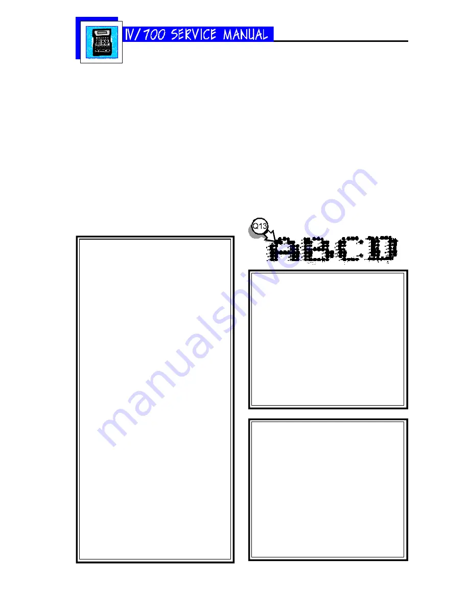
Q13 The I.V./700 is printing the correct mes-
sage but the characters are out of po-
sition and there are a lot of extra dots.
Why?
S13
The printhead is too far from the product
(see the scanned sample at right below). Ad-
just the printhead until it is closer to the box.
The faster the box travels, the closer the print-
head must be to the box.
Q14 After sitting idle for a few minutes, the
first dots printed in the message are
too small when the I.V./700 starts
printing again. Why?
S14
Undersized dots on startup can result from
two adjustments: dot size and first dot. These
variables need to be tested and set at the
same time to achieve a satisfactory solution.
Adjust the size of the first printed dots by
following the directions below.
Q14 I selected fixed speed and now my I.V./
700 prints backwards or random dots.
Why?
S14
The I.V./700 print direction is wrong. Change
the print direction by following the directions
below.
Q15 The I.V./700 is printing dots of differ-
ent sizes. Why?
S15
First, verify that the dot sizes identified on the
label on the bottom of the printhead match
those programmed into the unit, if not, change
them per the instructions below. If they do
match, you may have to increase or decrease
some settings to get the desired dot size.
First Dot Adjustment
1 Press and hold ALT + INFORMATION.
2 Plug in the barrel connector.
3 Release the keys when the LCD shows “In-
formation”.
4 Press SET-UP.
5 Press K. The LCD will prompt for the num-
ber of seconds that the printer will stand
idle.
6 Type in the amount of time and press
ENTER.
7 The first line of the LCD will show “1st Dot
Adjust:1” for the first valve (dot) at the top
of the printhead.
The second line of the LCD will prompt for
“Dot Adjustment”. If the first printed dot
was small in the sample print, increase the
value by 10 which will increase the size of
the first printed dot by valve 1.
If the first printed dot by valve 1 was full-
sized, DO NOT enter a new value: leave
the existing value and press ENTER.
8 The LCD will change to “1st Dot Adjust:2”
for valve 2. Repeat this process for all
valves.
9 After the seventh dot, press SET-UP. The
LCD will prompt for “Factory Setting”. Se-
lect “2-Yes”. Wait the time designated in
step 5 and make a print sample. If it is
satisfactory, this procedure is complete. If
the sample is not satisfactory, unplug the
barrel connector and repeat this procedure.
Setting the Print Direction
1 Press SET-UP.
2 Press F for "F-Print Direction." The LCD
will prompt for a Yes or No to fixed direc-
tion printing.
If you select 1-No, the LCD will return to
the Set-Up menu.
3 If you select 2-Yes, the LCD will ask you
to set the print direction.
4 Select a direction and press ENTER.
Changing All Printed Dot Sizes
1 Press SET-UP.
2 Press DOT SIZE. The LCD will prompt for
a dot diameter.
3 Scroll to a new dot diameter and press
ENTER.
Run some print samples with the new
dot diameter to see if the printing is im-
proved. If not, change the dot diameter
again and run more print samples.
Summary of Contents for I.V./700
Page 4: ...5750 212 Revision A Page 4 I V 700 Components...
Page 26: ...5750 212 Revision A Page 26 Hardware Block Diagram HBD1...
Page 30: ...5750 212 Revision A Page 30 Modular Parts Kits...
Page 31: ...5750 212 Revision A Page 31 Controller Assembly...
Page 32: ...5750 212 Revision A Page 32 Printhead Assembly...
Page 34: ...5750 212 Revision A Page 34...
Page 35: ...5750 212 Revision A Page 35...


