DI Lusso BSEN13240 R4 Euro Installation And Operating Instructions Manual Download Page 5

JINDLE04 Rev B 15/09/15 

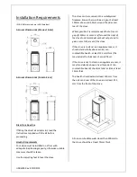
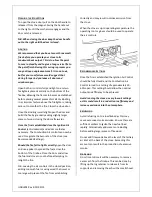
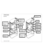
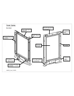
Installation Requirements 

(N.B. All dimensions are in Millimetres) 
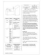
A

PPLIANCE 

D

IMENSIONS 

(S

TRAIGHT 

S

IDES


A

PPLIANCE 

D

IMENSIONS 

(C

URVED 

S

IDES


D

IRECT 

A

IR 

A

DAPTOR


If fitting the direct air adaptor kit, read the 
instructions supplied with the kit before 
proceeding. 

H

EARTH 

R

EQUIREMENTS


Your stove must be installed on a floor with 
adequate load-bearing capacity, otherwise suitable 
measures should be taken.  

Use the adjusting feet to level the stove. 

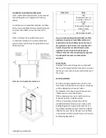
The stove can be recessed into a suitably sized 
fireplace. Ensure there is a free air gap of at least 
150mm above and 50mm around the sides and 
rear of the stove.  

Where possible it is recommended that a free air 
gap of 150mm or more is left around the sides of 
the stove to obtain maximum heat output and to 
gain access to the rear of the stove. 

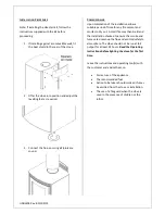
If the stove is to stand in an appliance recess, it 
should stand wholly above a solid, non-
combustible hearth, at least 125 mm thick (this 
may include the thickness of a solid floor).  

If the stove is not to stand in an appliance recess, it 
may stand wholly above a hearth made of non-
combustible board / sheet material or tiles, at least 
12mm thick.  

The hearth should extend at least 150 mm from 
the sides and rear of the stove, and at least 225 
mm from the front of the stove.  


All non-combustible walls closer than 300mm to 
the stove should be at least 75mm thick. 


Summary of Contents for BSEN13240 R4 Euro

Page 1: ...JINDLE04 Rev B 15 09 15 Wood Burning Stove Installation and Operating Instructions R4 Euro...

Page 2: ...ng Stove Appliance Mass 70kg Efficiency 79 Nominal Heat Output 4 9kW Mean Co Emission 13 O2 0 09 Mean OGC Emission 13 O2 99 mg m3 n Mean NOx as NO2 35 mg m3 n Mean Flue Gas Temperature 226 C Flue Gas...

Page 3: ...to notify your local building control body in advance of any work starting HEALTH AND SAFETY PRECAUTIONS Special care must be taken when installing the stove such that the requirements of the Health a...

Page 4: ...appliance should not be operated with the door open If fume emission does persist then the following action should be taken immediately Open Doors and windows to ventilate room Let the fire out or ej...

Page 5: ...0mm around the sides and rear of the stove Where possible it is recommended that a free air gap of 150mm or more is left around the sides of the stove to obtain maximum heat output and to gain access...

Page 6: ...metres above the hearth Any walls more than 50mm from the appliance may be reduced to a thickness of 75mm Ensure the inter connecting flue pipe also has adequate clearances to combustible materials FU...

Page 7: ...uld have a vertical height of at least 4 5 metres and should terminate in accordance with Table 2 If the chimney is believed to have previously served an open fire installation it is possible that the...

Page 8: ...f time for any fire cement and mortar to dry out A small fire may then be lit and the installation checked to ensure the smoke and fumes are drawn up the flue and emitted safely to atmosphere The stov...

Page 9: ...ove will burn cleanly and efficiently Therefore to avoid the disappointment of poor performance or dirty glass please familiarize yourself with the controls and their recommended settings before use T...

Page 10: ...mended Settings Should the fire fail to light correctly open the door and use a poker to spread the fuel across the bottom of the firebox Close the door and allow the fuel and stove to cool before att...

Page 11: ...rson Chimney and flueways it is important that the chimney flueways and any connecting pipe are swept regularly This means at least twice a year for Woodburning appliances Only wire centred sweeps bru...

Page 12: ...that Chimneys and flueways are clear A suitable fuel is being used There is an adequate air supply into the room An extractor fan is not fitted in the same room as the stove Flue draught is above mini...

Page 13: ...int forward the door has been hidden for illustrative purposes 2 Remove the log retainer by lifting it clear of the two support pins 3 Remove the baffle brick by lifting it up sliding it to the right...

Page 14: ...t in place turning both air controls to the fully open position clockwise and then gently pulling on the fascia to slide the cassette out from under the firebox N B DO NOT Remove the Air Valve Cassett...

Page 15: ...Side Panels Black HME04ARRT019 L R Stainless Steel HME04ARRT026 L R Curved Side Panels Black HME04ARRT020 L R Stainless Steel HME04ARRT029 L R Operating Tool HMR04ARRT025 Log Retainer HMR04ARRT009 Di...

Page 16: ...R04054 Glass Spacer Clip Bottom HMR04053 Door Handle HME04ARRT025 Knitted Fiberglass Tape Glass Spacer Clip Side HMR04055 Door Glass DLU04001 Door Catch Assembly HME04ARRT006 Door Chassis Assembly HME...

Page 17: ...ly HMR04ARRT005L Air Valve Cassette Front Plate HMR04024 Pushrod Assembly HME04ARRT021 Instruction Plate HME04080 Magnet FMAG10 5 3 2 CS Control Knob HMR04031 Control Facia Assembly HME04ARRT015 Starl...

Reviews: