DI Lusso BSEN13240 R4 Euro Installation And Operating Instructions Manual Download Page 10

JINDLE04 Rev B 15/09/15 

O

PENING THE 

S

TOVE 

D

OOR


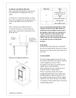
To open the stove door pull on the door handle to 
release it from the magnet. Swing the handle out 
to the right until the mechanism engages and the 
door catch is released.  

N.B. When closing the door keep the door handle 
out to the right until the door is closed. 

 
L

IGHTING


We recommend that you have two or three small 
fires before you operate your stove to its 
maximum heat output. This is to allow the paint 
to cure in steadily and to give a long service life to 
the paint finish. During this curing in process you 
may notice an unpleasant smell. It is non-toxic, 
but for your comfort we would suggest that 
during this period you leave all doors and 
windows open. 

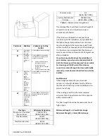
Open both air controls fully and light one or two 
firelighters placed centrally on the bottom of the 
firebox, allowing the flames to become established 
before placing several pieces of small dry kindling 
in a crisscross fashion above the firelighters, taking 
care not to smother the fire. Close the stove door.  

Once the kindling is well alight open the door and 
build the fire by gradually adding slightly larger 
pieces of wood, closing the door afterwards.


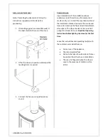
Once the fire is established close the Ignition Air 
Control

 (anti-clockwise) and add more fuel as 

necessary. The Combustion Air control can now be 
used to regulate the burn rate of the stove (see 
Recommended Settings).  

Should the fire fail to light correctly

 open the door 

and use a poker to spread the fuel across the 
bottom of the firebox. Close the door and allow 
the fuel and stove to cool before attempting to 
relight the fire. 

N.B. Leaving the air controls in the closed position, 
adding too much fuel or using wood that is wet or 
too large will prevent the fire from establishing 

correctly and may result in smoke emission from 
the stove. 

When the stove is up to operating temperature the 
operating tool or gloves should be used to operate 
the air controls. 


R

ECOMMENDED 

S

ETTINGS


Once the fire is established the Ignition Air Control 
should be fully closed and the Combustion Air 
Control turned to a setting of approximately 50 -
60% open. This setting should allow the nominal 
output and efficiency to be achieved. 

Avoid running the stove on very low air settings 
as this could result in a reduction in efficiency and 
increase emissions into the atmosphere.  

REFUELLING 

Avoid refueling on to a low firebed as this may 
cause excessive smoke emission. Ensure there are 
sufficient embers to ignite the new fuel load 
rapidly. Alternatively add some more kindling 
before adding larger pieces of firewood. 

Do not add firewood above the level of the tertiary 
air inlet at the back of the stove. Exceeding this 
amount can result in the production of excessive 
smoke. 

D

E

-A

SHING


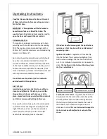
From time to time it will be necessary to remove 
excess ash from the firebox. This can be done by 
lifting up the log retainer to release it from its 
supports and removing the ash with a small shovel.  

Summary of Contents for BSEN13240 R4 Euro

Page 1: ...JINDLE04 Rev B 15 09 15 Wood Burning Stove Installation and Operating Instructions R4 Euro...

Page 2: ...ng Stove Appliance Mass 70kg Efficiency 79 Nominal Heat Output 4 9kW Mean Co Emission 13 O2 0 09 Mean OGC Emission 13 O2 99 mg m3 n Mean NOx as NO2 35 mg m3 n Mean Flue Gas Temperature 226 C Flue Gas...

Page 3: ...to notify your local building control body in advance of any work starting HEALTH AND SAFETY PRECAUTIONS Special care must be taken when installing the stove such that the requirements of the Health a...

Page 4: ...appliance should not be operated with the door open If fume emission does persist then the following action should be taken immediately Open Doors and windows to ventilate room Let the fire out or ej...

Page 5: ...0mm around the sides and rear of the stove Where possible it is recommended that a free air gap of 150mm or more is left around the sides of the stove to obtain maximum heat output and to gain access...

Page 6: ...metres above the hearth Any walls more than 50mm from the appliance may be reduced to a thickness of 75mm Ensure the inter connecting flue pipe also has adequate clearances to combustible materials FU...

Page 7: ...uld have a vertical height of at least 4 5 metres and should terminate in accordance with Table 2 If the chimney is believed to have previously served an open fire installation it is possible that the...

Page 8: ...f time for any fire cement and mortar to dry out A small fire may then be lit and the installation checked to ensure the smoke and fumes are drawn up the flue and emitted safely to atmosphere The stov...

Page 9: ...ove will burn cleanly and efficiently Therefore to avoid the disappointment of poor performance or dirty glass please familiarize yourself with the controls and their recommended settings before use T...

Page 10: ...mended Settings Should the fire fail to light correctly open the door and use a poker to spread the fuel across the bottom of the firebox Close the door and allow the fuel and stove to cool before att...

Page 11: ...rson Chimney and flueways it is important that the chimney flueways and any connecting pipe are swept regularly This means at least twice a year for Woodburning appliances Only wire centred sweeps bru...

Page 12: ...that Chimneys and flueways are clear A suitable fuel is being used There is an adequate air supply into the room An extractor fan is not fitted in the same room as the stove Flue draught is above mini...

Page 13: ...int forward the door has been hidden for illustrative purposes 2 Remove the log retainer by lifting it clear of the two support pins 3 Remove the baffle brick by lifting it up sliding it to the right...

Page 14: ...t in place turning both air controls to the fully open position clockwise and then gently pulling on the fascia to slide the cassette out from under the firebox N B DO NOT Remove the Air Valve Cassett...

Page 15: ...Side Panels Black HME04ARRT019 L R Stainless Steel HME04ARRT026 L R Curved Side Panels Black HME04ARRT020 L R Stainless Steel HME04ARRT029 L R Operating Tool HMR04ARRT025 Log Retainer HMR04ARRT009 Di...

Page 16: ...R04054 Glass Spacer Clip Bottom HMR04053 Door Handle HME04ARRT025 Knitted Fiberglass Tape Glass Spacer Clip Side HMR04055 Door Glass DLU04001 Door Catch Assembly HME04ARRT006 Door Chassis Assembly HME...

Page 17: ...ly HMR04ARRT005L Air Valve Cassette Front Plate HMR04024 Pushrod Assembly HME04ARRT021 Instruction Plate HME04080 Magnet FMAG10 5 3 2 CS Control Knob HMR04031 Control Facia Assembly HME04ARRT015 Starl...

Reviews: