background image


25 

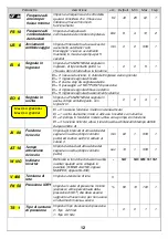
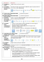
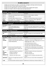
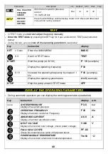
RICERCA GUASTI 

Verificare che l’inverter sia stato correttamente collegato alla linea di alimentazione 

Verificare che la  linea di alimentazione sia attiva 

Verificare che l’elettropompa sia stata correttamente collegata all’inverter 

Verificare che tutti i cavi e le connessioni siano funzionanti. 

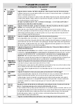
PROBLEMA 

La pompa non si accende 

Messaggio 

Causa 

intervento 

Nessuno 

Interruzione dell’alimentazione elettrica Ripristinare l’alimentazione elettrica 

Nessuno 

Fusibili bruciati 

Sostituire i fusibili 

Nessuno 

Intervento delle protezioni di linea 

Verificare la corretta taratura delle protezioni 

INPUT 
ERROR 

(solo modelli T/T) - I collegamenti LINEA 
e MOTORE sono stati invertiti 

Verificare i collegamenti LINEA e MOTORE e 
ricollegare correttamente 

PROBLEMA 

Intervento dell’ interruttore differenziale  a protezione della linea di alimentazione 
dell’inverter 

Messaggio 

Causa 

intervento 

Nessuno 

L’interruttore differenziale è 
inadeguato all’alimentazione 
dell’inverter 

Sostituire l’interruttore differenziale con un modello 
idoneo alle componenti pulsanti e in corrente continua 
(classe A) 

PROBLEMA 

La pompa non si avvia 

Messaggio 

Causa 

intervento 

OFF 

La pompa è fuori servizio (messa fuori 
servizio manuale) 

Rimettere la pompa in servizio premendo il tasto 
START 

PROBLEMA 

La pompa si è arrestata e non riparte 

Messaggio 

Causa 

intervento 

OVER 
CURRENT 

eccesso di assorbimento di corrente 
rispetto al valore settato ( parametro A 
in BASE PARAMETER) 

Controllare il corretto settaggio della corrente 

Controllare che la tensione sotto carico non sia mai 
troppo bassa (min – 15%) 

che l’elettropompa ruoti libera 

che il senso di rotazione sia corretto 

che i cavi siano correttamente dimensionati 

CURRENT 
LIMIT 

Grave eccesso di assorbimento di 
corrente, che eccede la capacità del 
modulo inverter 

controllare che l’elettropompa non sia bloccata 

ridurre l’accelerazione del motore (parametro di 
fabbrica) 

DRY 
RUNNING 

 (DRY 
RUNNING PF)

Mancanza di acqua in aspirazione 

pompa non adescata 

aspirazione ostruita 

rotazione inversa del motore 

verificare la presenza di acqua in aspirazione 

adescare la pompa 

controllare l’aspirazione 

invertire il senso di rotazione del motore della 
pompa 

LOW PRESS 

Il sistema non raggiunge la pressione 
minima 

verificare che non vi siano rotture nelle tubazioni. 

 LOW 

Scostamento della tensione superiore a  Stabilizzare la tensione per mantenerla dentro la 

Summary of Contents for DGFIT Series

Page 1: ...A AT TI IO ON N E ET T D D E EN NT TR RE ET TI IE EN N Pag 83 D DG GF FI IT T I IN NV VE ER RT TE ER R VARIATORE ELETTRONICO DI FREQUENZA VARIABLE FREQUENCY DRIVE VARIADOR ELECTR NICO DE FRECUENCIA IN...

Page 2: ...set 14 o Visualizzazione della matricola e della versione firmware 14 o Adescamento e prima messa in marcia 14 o Settaggio di gruppo a 2 pompe SENZA sensore di flusso 15 o Settaggio di gruppo a 2 pomp...

Page 3: ...conformi alle norme Prima di rimuovere il coperchio dell inverter o iniziare interventi su di esso necessario scollegare l impianto dalla rete elettrica ed attendere almeno 5 minuti affinch i condens...

Page 4: ...e norme SVITARE NON SVITARE COLLEGAMENTI ELETTRICI DI POTENZA Collegare i cavi R S T della linea di alimentazione al morsetto LINE indicato sotto Collegare i cavi U V W del motore al morsetto MOTOR in...

Page 5: ...vi del sensore di pressione al morsetto PRESS SENS per SENSORE 4 20 mA per SENSORE 0 5 4 5 V PR E SS SENS 3 2 1 V dc 4 20m A 0 4 5 V V F low N O F low C 4 5 FLO WSE NS PR E SS SENS 3 2 1 V dc 4 20m A...

Page 6: ...D D V D D R S485 COLLEGAMENTO DEI SEGNALI IN INGRESSO E IN USCITA es segnale di livello e segnale di allarme U V W 1 2 V 24Vdc 2 1 P O W E R SU P P LY F AN O UTP U T V 24Vdc MOTOR N O C 4 3 2 1 INPUT...

Page 7: ...N C PRESS SENS 3 2 1 V dc 4 20m A 0 4 5 V V Flow N O F low C 4 5 FLOW SENS LINE R S T V D D V D D RS485 DESCRIZIONE DELLA TASTIERA 1 Pulsante ACCENSIONE SPEGNIMENTO 2 LED verde di marcia 3 LED rosso d...

Page 8: ...ettati in fase di installazione ADV PARAMETRI AVANZATI per la configurazione dettagliata dell inverter INSP PARAMETRI DI ISPEZIONE visualizzano le ore di lavoro il numero di avviamenti lo storico degl...

Page 9: ...PER FLUSSO NULLO RF RAPIDITA DI REAZIONE INVERTER FWS PRESENZA SENSORE DI FLUSSO OF FREQUENZA DI SPEGNIMENTO FS FREQUENZA DI COMMUTAZIONE DEL MODULO US AVVIAMENTI ANTI BLOCCAGGIO EI SEGNALE IN INGRES...

Page 10: ...FLUSSO Per arrestare correttamente l inverter al cessare della richiesta dell utenza Al primo settaggio della pressione necessario definire la FREQUENZA DI SPEGNIMENTO corrispondente alla portata min...

Page 11: ...rcia a secco sec 10 1 100 1 P PF F 1 10 0 COSFI minimo Imposta il valore minimo del fattore di potenza cosfi sotto il quale l inverter arresta la pompa 0 50 0 50 0 99 0 01 T TP PF F 0 0 Ritardo arrest...

Page 12: ...ita di tipo contatto pulito con logica NO 0 0 3 1 EI 0 nessuna funzione il rel non viene attivato EI 1 uscita di allarme il rel si attiva se l inverter va in allarme EI 2 pompa in funzione il rel si a...

Page 13: ...SIC X 3 Scorro sino al MENU TEST TEST START Avvio la pompa a 30 Hz P 1 5 esempio Visualizzare la frequenza di funzionamento F 30 X 10 Incrementare la frequenza di funzionamento a passi di 1 Hz F 40 es...

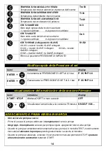
Page 14: ...MPIANTO Modifica rapida della Pressione di set tasto istruzione display ENTER Incrementa la PRESSIONE DI SET di 0 1 bar P 3 5 P 3 6 ENTER Decrementa la PRESSIONE DI SET di 0 1 bar P 3 5 P 3 4 visualiz...

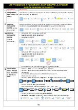
Page 15: ...rsi in TEST ed avviare con START Leggere e registrare la pressione Arrestare con STOP La condizione con pressione maggiore quella corretta 3 PROTEZIONE DELLA POMPA DALLA MARCIA A SECCO con COSFI Porta...

Page 16: ...SPEGNIMENTO 9 PROTEZIONE DELLA POMPA DALLA MARCIA A SECCO con COSFI v procedura al punto 3 10 CONTROLLO DELLA PRESSIONE MINIMA DI FUZIONAMENTO Settare il parametro PD nel menu ADV alla della pressione...

Page 17: ...DI FLUSSO 6a VERIFICA DELLA ROTAZIONE POMPA pompe sommerse v SETTAGGIO ED AVVIAMENTO DI UN GRUPPO A 2 POMPE SENZA SENSORE DI FLUSSO 7 SETTAGGIO DELLA SCALA DEL SENSORE DI PRESSIONE v SETTAGGIO ED AVVI...

Page 18: ...uto e l inverter torna in funzione automaticamente HIGH TEMP BOX La temperatura interna dell inverter ha raggiunto la soglia di attenzione Viene automaticamente limitata la frequenza massima ma l inve...

Page 19: ...er SLAVE diventano indipendenti e continuano ad operare indipendentemente LIMITI DI UTILIZZO pericolo di incendio esplosione gli inverter DGFIT NON SONO ADATTI ad operare in ambienti con pericolo di e...

Page 20: ...essere installato In un locale riparato dalle intemperie Il pi vicino possibile alla pompa che comanda Deve avere lo spazio minimo superiore ed inferiore indicato nelle DIMENSIONI e PESI per l access...

Page 21: ...lettropompa dovranno essere a 3 conduttori 2 fasi terra nelle applicazioni monofase a 4 conduttori 3 fasi terra nelle applicazioni trifase la SEZIONE DEI CAVI dovr essere dimensionata in funzione dell...

Page 22: ...ter quando la richiesta da parte dell utenza terminata necessario definire la FREQUENZA DI SPEGNIMENTO parametro OF Se viene modificata la PRESSIONE DI SET la FREQUENZA DI SPEGNIMENTO sar automaticame...

Page 23: ...secondi questa fase preavvisa che l inverter sta per entrare in funzione Trascorsi 10 secondi la fase di STARTING termina e DGFIT torna nelle stesse condizioni di funzionamento in cui era al momento d...

Page 24: ...allarmi Per SCORRERE i parametri utilizzare i tasti Per ACCEDERE ed USCIRE dai parametri utilizzare i tasti INSP WH ORE DI FUNZIONAMENTO DELLA POMPA Ore di funzionamento della pompa motore in funzion...

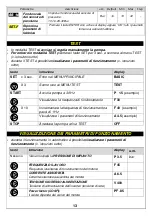
Page 25: ...se A PROBLEMA La pompa non si avvia Messaggio Causa intervento OFF La pompa fuori servizio messa fuori servizio manuale Rimettere la pompa in servizio premendo il tasto START PROBLEMA La pompa si arre...

Page 26: ...enza di acqua in aspirazione o il funzionamento del segnale di livello EXT OFF Messa fuori servizio mediante segnale esterno con Ingresso Segnale esterno attivo Rimettere in servizio mediante il segna...

Page 27: ...nella calibrazione premere TEST Sul display appare la scritta SP 5 0 Portare la pressione di impianto al valore richiesto sul display 5 0 bar avviando la pompa e regolando la velocit sino a raggiunge...

Page 28: ...nno decadere la garanzia sul prodotto che copre un periodo di 24 mesi dalla data di acquisto SMALTIMENTO Per lo smaltimento dei particolari che compongono i quadri DGBOX attenersi alle norme e leggi i...

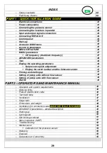
Page 29: ...ent 41 Display the serial number and the firmware version 41 o Priming and starting up 41 o Setting of pump units without flow sensor 42 o Setting of pump units with flow sensor 44 o Alarms 45 PART 2...

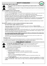
Page 30: ...rounding comply with the Standards Before removing the inverter cover or starting interventions on it the system must be disconnected from the mains electricity and you must wait for 5 mins until the...

Page 31: ...EN DO NOT REMOVE POWER CONNECTIONS Wire the motor cables U V W to the terminal MOTOR as shown below Wire the line cables R S T to the terminal LINE as shown below U V W 1 2 V 24Vdc 2 1 PO W E R SUPP L...

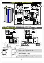
Page 32: ...485 Wire the pressure sensor cables to terminals PRESS SENS for SENSOR 4 20 mA for SENSOR 0 5 4 5 V PR E SS SENS 3 2 1 V dc 4 20m A 0 4 5 V V F low N O F low C 4 5 FLO WSE NS PR E SS SENS 3 2 1 V dc 4...

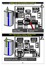
Page 33: ...FLO WSENS LINE R S T V D D V D D R S485 INPUT AND OUTPUT SIGNAL CONNECTIONS e g level probe and alarm signal U V W 1 2 V 24Vdc 2 1 P O W E R SU P P LY F AN O UTP U T V 24Vdc MOTOR N O C 4 3 2 1 INPUT...

Page 34: ...3 2 1 INPUT OUTPUT C N C PRESS SENS 3 2 1 V dc 4 20m A 0 4 5 V V Flow N O F low C 4 5 FLOW SENS LINE R S T V D D V D D RS485 CONTROL PANEL 1 START STOP button 2 Green LED status 3 Red LED power 4 Dis...

Page 35: ...s must necessarily be set during installation ADV ADVANCED PARAMETERS for the configuration of the drive INSP INSPECTION PARAMETERS you can display the hours of work the number of starts alarm history...

Page 36: ...ls TP RESTART INTERVAL FOR DRY RUNNING TF STOP DELAY FOR NO FLOW RF INVERTER REACTIVITY FWS FLOW SENSOR OF OFF FREQUENCY FS MODULE SWITCHING FREQ US NO GRIP STARTUPS EI INPUT SIGNAL EO OUTPUT SIGNAL A...

Page 37: ...stop the inverter at zero demand At the first pressure setting you must define the SHUTDOWN FREQUENCY frequency at the minimum working flow or shutdown flow the shutdown flow must be proportionate to...

Page 38: ...DELAY FOR DRY RUNNING Sets the pump stop delay under dry running conditions sec 10 1 100 1 P PF F 1 10 0 MINIMUM POWER FACTOR Sets the minimum value for the power factor below which the inverter stops...

Page 39: ...FUNCTION clean contact type NO logic 0 0 3 1 EO 0 NO FUNCTION the state of the output is never activated EO 1 ALARM OUTPUT condition of stop due to fault EO 2 PUMP OPERATING OUTPUT there is at least...

Page 40: ...ST START Start the pump at 30 Hz P 1 5 example Display the operating frequency F 30 X 10 Increase the operating frequency by steps of 1 Hz F 40 example Display the operating parameters A 4 5 example S...

Page 41: ...ack to the parameter SYSTEM PRESSURE P 3 5 bar Set pressure quick adjustment tasto istruzione display ENTER To increase the SET PRESSURE by 0 1 bar P 3 5 P 3 6 ENTER To decrease the SET PRESSURE by 0...

Page 42: ...record the pressure Stop the pump key START STOP The right rotation is the one with the higher pressure 3 DRY RUNNING PROTECTION THROUGH PARAMETER COSPHI Go to TEST mode start the pump key START STOP...

Page 43: ...n press ENTER to confirm the switch off frequency 9 DRY RUNNING PROTECTION THROUGH PARAMETER COSPHI See procedure at point 3 10 SETTING THE MINIMUM WORKING PRESSURE Set the parameter Pd in ADV menu at...

Page 44: ...of a 2 PUMPS UNIT WITHOUT FLOW SENSOR 6a PUMP ROTATION CHECK submersible pumps See SETTING AND STARTING UP of a 2 PUMPS UNIT WITHOUT FLOW SENSOR 7 SETTING THE PRESSURE SENSOR RANGE See SETTING AND ST...

Page 45: ...tomatic mode HIGH TEMP BOX The inverter internal temperature has reached the attention threshold It is automatically limited the maximum frequency but the drive continues to run the error is reset bel...

Page 46: ...operating data and activates and deactivates the SLAVE as needed If the MASTER is turned off the SLAVE becomes independent and will continue to operate independently WORKING LIMITS fire explosion inv...

Page 47: ...les DGFIT must be installed In a ventilated room protected from the elements and from exposure to the sun Vertically as close as possible to the pump that controls Must have minimum space upper and lo...

Page 48: ...n compliance with Standards Check that the plate data is that required and suitable for the system The power supply cable and the connection cable between the inverter and the motor must have o 3 wire...

Page 49: ...l be automatically updated to the new operating pressure It is possible during operation update at any time the OFF FREQUENCY You can define the OFF FREQUENCY directly editing the parameter in the ADV...

Page 50: ...n OUT OF SERVICE mode if at the time of the last shutdown was OUT OF SERVICE OFF In case of accidental fall of the power line if it DGFIT was in serivce when the power returns it automatically returns...

Page 51: ...ory of the inverter operating hours number of starts alarm recording to scroll the parameters use the keys to access and exit the parameters use the keys INSP WH OPERATING HOURS Operating hours with t...

Page 52: ...t of service placed manually out of service Put the pump back into service by pushing START PROBLEM The pump stopped and fails to re start Messaggio Causa intervento OVER CURRENT overcurrent absorptio...

Page 53: ...signal input on Make sure there is water at suction or check level signal operation EXT OFF Placing out of service by means of external signal Check the external signal P NC No pressure signal or out...

Page 54: ...displayed value 5 0 bar by starting the pump and adjusting the pump speed until you reach 5 0 bar see below If the pump is not able to reach 5 0 bar reduce the required pressure by pressing the button...

Page 55: ...original spare parts tampering or improper use making the warranty null and void DISPOSAL For the disposal of DGBOX components follow the Standards and Laws in force in the countries where the unit is...

Page 56: ...i n de serie y firmware 68 o Cebado y primera puesta en marcha 68 o Programaci n del grupo con dos bombas SIN sensor de flujo 69 o Programaci n del grupo con dos bombas CON el sensor de flujo 71 o Ala...

Page 57: ...A para aplicaciones domesticas y en clase B para aplicaciones industriales y de puesta a tierra conformes a las normas establecidas Antes de quitar la tapa del inversor o empezar a actuar sobre l hab...

Page 58: ...erra conformes a las normas establecidas DESTORNILLAR NO DESTORNILLAR CONEXIONES EL CTRICAS DE POTENCIA Conectar los cables R S T de la l nea de alimentaci n a terminal LINE Conectar los cables U V W...

Page 59: ...85 Conectar el cable del sensor de presi n al terminal PRESS SENS SENSOR 4 20 mA SENSOR 0 5 4 5 V PR E SS SENS 3 2 1 V dc 4 20m A 0 4 5 V V F low N O F low C 4 5 FLO WSE NS PR E SS SENS 3 2 1 V dc 4 2...

Page 60: ...4 5 FLO WSENS LINE R S T V D D V D D R S485 CONEXI N DE LAS SE ALES At se al de nivel y se al de alarma U V W 1 2 V 24Vdc 2 1 P O W E R SU P P LY F AN O UTP U T V 24Vdc MOTOR N O C 4 3 2 1 INPUT O UTP...

Page 61: ...ESS SENS 3 2 1 V dc 4 20m A 0 4 5 V V Flow N O F low C 4 5 FLOW SENS LINE R S T V D D V D D RS485 DESCRIPCI N DEL TECLADO 8 Pulsador de ENCENDIDO APAGADO 9 LED rojo de conexi n en red 10 LED verde de...

Page 62: ...nfiguraci n detallada del inversor INSP Son los PAR METROS DE INSPECCI N visualizan las horas de trabajo el n mero de puestas en marcha el archivo hist rico de las alarmas etc TEST La modalidad TEST p...

Page 63: ...O PARADA POR FLUJO NULO RF RAPIDEZ DE REACCI N INVERSOR FWS PRESENCIA SENSOR DE FLUJO OF FRECUENCIA DE APAGADO FS FRECUENCIA DE CONMUTACI N DEL M DULO US PUESTAS EN MARCHA ANTIBLOQUEO EI SE AL DE ENTR...

Page 64: ...correctamente el inversor al terminar la demanda del usuario A la primera programaci n de la presi n es necesario definir la FRECUENCIA DE CORTE correspondiente al caudal m nimo de funcionamiento caud...

Page 65: ...100 1 P PF F 1 10 0 FACTOR DE POTENCIA M NIMO s lo modelos T T Programa el valor m nimo del factor de potencia por debajo del cual el inversor detiene la bomba para evitar la marcha en seco 0 50 0 50...

Page 66: ...na funci n el rel no es activado EO 1 salida de alarma el rel se activa si el inversor entra en alarma EO 2 bomba en funcionamiento el rel se activa si la bomba est en funcionamiento EO 3 funci n reci...

Page 67: ...instrucci n display SET x 3 sec acceder al MEN PRINCIPAL BASIC X 3 desplazarse hasta el men TEST TEST START poner en marcha la bomba 30 Hz P 1 5 esempio Visualizar la frecuencia de funcionamiento F 3...

Page 68: ...sores SLAVE1 y SLAVE2 conectados S1 S2 Volver al par metro PRESI N DEL SISTEMA Modificaci n r pida de la presi n programada tecla instrucci n display ENTER Aumenta la presi n de ajuste de 0 1 bar P 3...

Page 69: ...en TEST y poner en marcha con START Leer y registrar la presi n Parar con STOP La condici n con m s presi n es la correcta 3 PROTECCI N DE LA BOMBA CONTRA LA MARCHA EN SECO con COSFI Situarse en TEST...

Page 70: ...ECUENCIA DE ACABADO 9 PROTECCI N DE LA BOMBA CONTRA LA MARCHA EN SECO con COSFI v procedimiento en el punto 3 10 CONTROL DE LA PRESI N M NIMA DE FUNCIONAMIEN TO Programar el par metro PD en el men ADV...

Page 71: ...ENSOR DE FLUJO 6a CONTROL ROTACI N DE LA BOMBA bombas sumergidas v PROGRAMACI N Y PUESTA EN MARCHA DE UN GRUPO DE 2 BOMBAS SIN SENSOR DE FLUJO 7 PROGRAMACI N DE LA ESCALA DEL SENSOR DE PRESI N v PROGR...

Page 72: ...del inversor ha alcanzado el umbral de la atenci n la frecuencia m xima es limitada autom ticamente pero el inversor sigue funcionando OVER TEMP BOX La temperatura interna del inversor ha alcanzado e...

Page 73: ...os datos de funcionamiento activando y desactivando los inversores SLAVE seg n las necesidades Si el inversor MASTER es apagado los inversores SLAVE vuelven a ser aut nomos y siguen funcionando indepe...

Page 74: ...ones y pesos para el acceso y la refrigeraci n En posici n vertical recibir n de las vibraciones nocivas para las plantas No funciona en la humedad relativa polvo o alta DEP SITO AUTOCLAVE acumula agu...

Page 75: ...i n La secci n del cable de alimentaci n del inversor y del cable de conexi n entre inversor y electrobomba deber dimensionarse en funci n de la tensi n 230V monof sico 230V trif sico y 400V trif sico...

Page 76: ...CONMUTACI N DEL M DULO Programa la frecuencia de conmutaci n del m dulo de potencia En caso de cable de potencia largo sin filtro sinusoidal dicha frecuencia deber reducirse al valor m nimo US PUESTA...

Page 77: ...YPRES se encontraba EN SERVICIO ON al restablecerse la red vuelve autom ticamente EN SERVICIO ON Para poner EN SERVICIO FUERA DE SERVICIO STEADYPRES pulsar la tecla START STOP En las aplicaciones con...

Page 78: ...or los par metros utilizar las teclas Para acceder y salir de los par metros utilizar las teclas INSP WH HORAS DE FUNCIONAMIENTO DE LA BOMBA Horas de funcionamiento de la bomba motor en funcionamiento...

Page 79: ...er a poner la bomba en servicio pulsando la tecla START PROBLEMA La bomba se ha detenido y no vuelve a ponerse en marcha Mensaje Causa Soluci n OVER CURRENT Exceso de absorci n de corriente respecto a...

Page 80: ...mediante se al externa con Entrada Se al externa activa Volver a poner en servicio mediante la se al externa P NC se al de presi n ausente o fuera de cobertura Compruebe las conexiones del sensor de...

Page 81: ...ci n sea nula Pulsar la tecla SET TEST para confirmar la presi n nula SP 5 0 Poner en marcha la bomba pulsando la tecla START la bomba se pone en marcha con la frecuencia m nima SP 5 0 Aumentar la fre...

Page 82: ...n que la garant a del producto que cubre un periodo de 24 meses desde la fecha de compra pierda su validez ELIMINACI N Para llevar a cabo la eliminaci n de las piezas que componen los paneles DGBOX se...

Page 83: ...ionnement 94 o Modification rapide de la pression de SET 95 o Affichage de la version firmware FW 94 o Amor age et premi re mise en marche 94 o R glage et d marrage d un groupe 2 pompes SANS capteur d...

Page 84: ...tiques ou bien B pour applications industrielles et d une mise la terre conformes aux r glementations en vigueur Avant de retirer le couvercle du convertisseur ou d intervenir sur celui ci il est n ce...

Page 85: ...vigueur DEVISSER PAS DEVISSER RACCORDEMENTS LECTRIQUES DE PUISSANCE Connectez les c bles de la ligne d alimentation R S T la borne LINE illustr ci dessous Connectez les c bles du moteur U V W la borne...

Page 86: ...D D R S485 Connectez les c bles du capteur de pression la borne PRESS SENS Capteur 4 20 mA Capteur 0 5 4 5 V PR E SS SENS 3 2 1 V dc 4 20m A 0 4 5 V V F low N O F low C 4 5 FLO WSE NS PR E SS SENS 3...

Page 87: ...D D V D D R S485 RACCORDEMENT DES SIGNAUX D INPUT OUTPUT par ex signal de niveau signal d alarme lumineux U V W 1 2 V 24Vdc 2 1 P O W E R SU P P LY F AN O UTP U T V 24Vdc MOTOR N O C 4 3 2 1 INPUT O U...

Page 88: ...INPUT OUTPUT C N C PRESS SENS 3 2 1 V dc 4 20m A 0 4 5 V V Flow N O F low C 4 5 FLOW SENS LINE R S T V D D V D D RS485 DESCRIPTION DU CLAVIER 1 Bouton START STOP 2 DIODE rouge de mise en r seau 3 DIO...

Page 89: ...e ou d arr ter manuellement la pompe touche START STOP et de modifier la fr quence pas de 1 Hz En outre elle permet de contr ler les param tres de fonctionnement du moteur et du convertisseur ATTENTIO...

Page 90: ...DIT DE R ACTION DU CONVERTISSEUR FWS PR SENCE DU CAPTEUR DE DEBIT OF FREQUENCE D ARRET FS FR QUENCE DE COMMUTATION DU MODULE US D MARRAGES ANTI BLOCAGE EI SIGNAL EN ENTR E EO SIGNAL EN SORTIE AI FONCT...

Page 91: ...D BIT Pour arr ter correctement le convertisseur la fermeture de l utilisateur Au premier r glage de la pression il est n cessaire de d finir la FR QUENCE D ARRET correspondante au d bit minimal de fo...

Page 92: ...UR DE PUISSANCE MINIMUM tablit la valeur minimum du facteur de puissance cosfi sous laquelle le convertisseur arr te la pompe pour viter la marche sec 0 50 0 50 0 99 0 01 T TP PF F 0 0 RETARD ARR T PO...

Page 93: ...E tablit la FONCTION du signal en sortie de type contact propre NO ou NC 0 0 3 1 EO 0 aucune fonction le relais n est pas activ EO 1 sortie d alarme le relais s active si le convertisseur entre en ala...

Page 94: ...fonctionnement pas de 1 Hz F 40 esempio afficher les param tres de fonctionnement A 4 5 esempio STOP la fin du TEST arr ter la pompe OFF ATTENTION sur le convertisseur SLAVE la commande TEST n est pas...

Page 95: ...tour au param tre PRESSION DE SYST ME Modification rapide de la pression de SET tasto istruzione display ENTER Pour augmenter de 0 1 bar P 3 5 P 3 6 ENTER Pour diminuer de 0 1 bar P 3 5 P 3 4 Affichag...

Page 96: ...ST et d marrer avec START Lire et enregistrer la pression Arr ter avec STOP La condition avec la pression sup rieure est celle correcte 3 PROT CTION DE LA POMPE CONTRE LA MARCHE SEC avec COSFI Se port...

Page 97: ...PURE 9 PROT CTION DE LA POMPE CONTRE LA MARCHE SEC avec COSFI v proc dure au point 3 10 CONTR LE DE LA PRESSION MINIMUM DE FONCTIONNEMEN T R gler le param tre PD dans le menu ADV au de la pression de...

Page 98: ...RIFICATION ROTATION POMPE pompes immerg es v R GLAGE ET D MARRAGE D UN GROUPE 2 POMPES SANS CAPTEUR DE D BIT 7 R GLAGE DE L CHELLE DU CAPTEUR DE PRESSION v R GLAGE ET D MARRAGE D UN GROUPE 2 POMPES S...

Page 99: ...du convertisseur a attaint le seuil d attention La fr quence maximale est automatiquement limit e mais le convertisseur continue fonctionner l erreur s annule sous les 60 C OVER TEMP BOX La temp ratur...

Page 100: ...onctionner ind pendamment LIMITES D UTILISATION danger d incendie explosion les convertisseurs DGFIT NE SONT PAS APPROPRI S au pompage de liquides inflammables ou travailler dans des milieux qui pr se...

Page 101: ...s pr s possible de la pompe qui commande Doit avoir l espace minimum sup rieur et inf rieur indiqu dans les DIMENSIONS et POIDS pour le l acc s et le refroidissement En position verticale il ne doit p...

Page 102: ...ble de raccordement entre le convertisseur et l lectropompe devra tre dimensionn e en fonction de la tension 230V monophas 230V triphas 400V triphas de la puissance de l lectropompe de la longueur des...

Page 103: ...ON AU r tablissement du r seau il reviendra automatiquement EN SERVICE ON Pour mettre EN SERVICE HORS SERVICE DGFIT appuyer sur START STOP Dans les applications avec convertisseur en parall le MASTER...

Page 104: ...d marrages l enregistrement des alarmes INSP WH HEURES DE FONCTIONNEMENT DE LA POMPE Heures de fonctionnement de la pompe moteur en fonction TH HEURES DE L ALLUMAGE DU CONVERTISSEUR Heures de fonctio...

Page 105: ...ropompe tourne librement que le sens de rotation soit correct que les c bles soient correctement dimensionn s Probl me Message Cause intervention La pompe si s est arr t e et ne red marre pas CURRENT...

Page 106: ...ieures 2 l min Trouver les fuites et les bloquer aucun Panne ou obstruction au capteur de d bit Inspecter et v rifier le capteur de d bit aucun Param trage de la fr quence minimum OFF FREQUENCY trop b...

Page 107: ...stallation est nulle Appuyer la touche SET TEST pour confirmer la pression nulle SP 5 0 Mettre la pompe en marche en appuyant la touche START la pompe d marrera la fr quence minimale SP 5 0 Augmenter...

Page 108: ...e alt ration annulent la garantie sur le produit qui couvre une p riode de 24 mois partir de la date d achat MISE LA D CHARGE Pour le traitement des pi ces formant les tableaux DGBOX suivre les normes...

Reviews: