background image

36

2

Hardware Installation

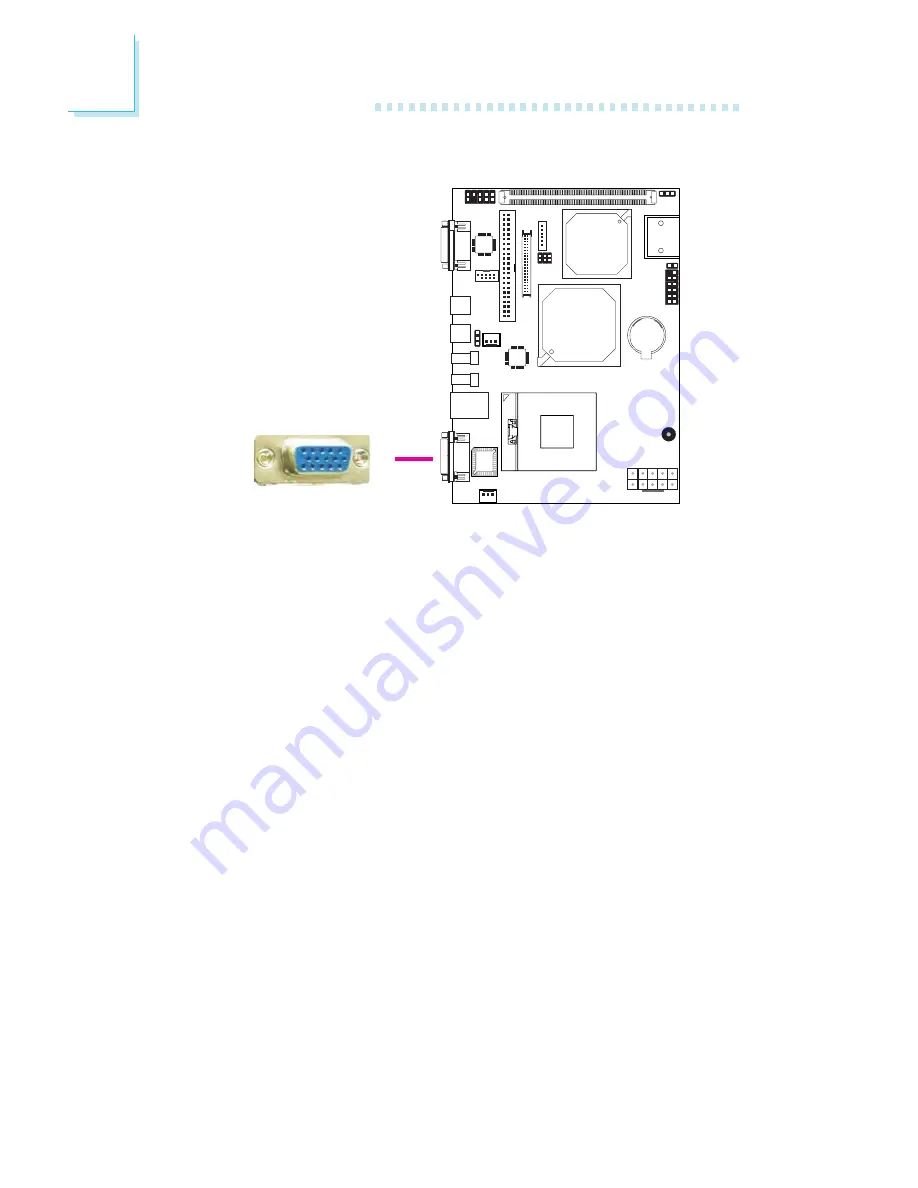
VGA Port

The VGA port is used for connecting a VGA monitor. Connect the
monitor’s 15-pin D-shell cable connector to the VGA port (Blue).
After you plug the monitor’s cable connector into the VGA port,
gently tighten the cable screws to hold the connector in place.

BIOS Setting

Configure the onboard VGA in the Advanced Chipset Features
submenu of the BIOS. Refer to chapter 3 for more information.

Driver Installation

Install the graphics driver. Refer to chapter 4 for more information.

1

LAN

X

Summary of Contents for CT930-B

Page 1: ...CT930 B ECX Board User s Manual 935 CT9303 050G I01910743...

Page 2: ...se of this manual and specifically disclaims any ex press or implied warranties of merchantability or fitness for any par ticular purpose The user will assume the entire risk of the use or the results...

Page 3: ...ticular installation If this equipment does cause harmful interference to radio or television reception which can be determined by turning the equipment off and on the user is encouraged to try to cor...

Page 4: ...yout Mechanical Diagram System Memory CPU Jumper Settings Rear Panel I O Ports I O Connectors Chapter 3 BIOS Setup Award BIOS Setup Utility Updating the BIOS Chapter 4 Supported Softwares Drivers for...

Page 5: ...and product specifica tions 2 The warranty is void if the product has been subjected to physi cal abuse improper installation modification accidents or unau thorized repair of the product 3 Unless ot...

Page 6: ...ends Important Electrostatic discharge ESD can damage your processor disk drive and other components Perform the upgrade in struction procedures described at an ESD workstation only If such a station...

Page 7: ...iffer in accordance to the sales region or models in which it was sold For more infor mation about the standard package in your region please contact your dealer or sales representative Before Using t...

Page 8: ...ximum of 2GB system memory using 256Mbit 512Mbit or 1Gbit technology for x8 and x16 devices Award BIOS 4Mbit flash memory Supports ACPI specification and OS Directed Power Manage ment Wake On Events i...

Page 9: ...data transmission IEEE 802 3 10 100Mbps and IEEE 802 3ab 1Gbps compliant Supports 2 SATA Serial ATA interfaces which are compliant with SATA 1 0 specification SATA speed up to 1 5Gb s One 44 pin IDE...

Page 10: ...T ECX1 Daughterboard optional 0o C to 60o C 10 to 90 10 layers ECX form factor 10 5cm 4 14 x 14 6cm 5 75 1 daughterboard connector for EXT ECX1 daughterboard Chrontel CH7307C DVI transmitter chip 2 US...

Page 11: ...er rate delivers bandwidth of 4 3 GB per second and beyond That is twice the speed of the conven tional DDR without increasing its power consumption DDR2 SDRAM modules work at 1 8V supply compared to...

Page 12: ...rts 480Mb second bandwidth providing a marked improvement in device transfer speeds between your com puter and a wide range of simultaneously accessible external Plug and Play peripherals This feature...

Page 13: ...lows your system to automatically power on on the set date and time The system board is designed to meet the ACPI Advanced Configuration and Power Interface speci fication ACPI has energy saving featu...

Page 14: ...14 2 Hardware Installation Chapter 2 Hardware Installation System Board Layout Component side Solder side...

Page 15: ...15 2 Hardware Installation Mechanical Diagram CT930 B component side 146 00 8 90 133 90 3 18 105 00 95 22 8 90 133 90 41 02 3 18 12 98 95 22 67 32 6 U 22053 00...

Page 16: ...16 2 Hardware Installation CT930 B solder side...

Page 17: ...17 2 Hardware Installation BIOS Setting Configure the system memory in the Advanced Chipset Features submenu of the BIOS System Memory SODIMM...

Page 18: ...es 3 Locate the SODIMM socket on the board 4 Note the key on the socket The keying mechanism ensures the module can be plugged into the socket in only one way 5 Grasping the module by its edges insert...

Page 19: ...dge of the module will almost completely disappear inside the socket Note The board used in the following illustrations may not resemble the actual one These illustrations are for reference only 7 Pus...

Page 20: ...n this section may not resemble the actual one These illustrations are for reference only 1 Make sure the PC and all other peripheral devices connected to it has been powered down 2 Disconnect all pow...

Page 21: ...are not supported Installing an incompatible processor will cause severe damage to both the proces sor and system board 2 Handle the CPU by its edges and avoid touching the pins 6 Insert the CPU into...

Page 22: ...Note Use only certified fan and heat sink Your fan and heat sink package usually contains the fan and heat sink assembly and an installation guide If the in stallation procedure in the installation g...

Page 23: ...e strongly recommend using this type of fan heat sink assembly because it provides adequate cooling to the components of the system board Turn each Phillips head screw half way down first to initially...

Page 24: ...lues stored in the ROM BIOS To load the default values stored in the ROM BIOS please follow the steps below 1 Power off the system and unplug the power cord 2 Set JP1 pins 2 and 3 to On Wait for a few...

Page 25: ...use to wake up the system BIOS Setting Configure the PS 2 keyboard mouse wake up function in the Inte grated Peripherals submenu Super IO Device section of the BIOS Refer to chapter 3 for more informa...

Page 26: ...2 3 4 5 6 1 2 1 4 On 12V 2 5 On 5V 3 6 On 3 3V X JP2 is used to select the power supplied to the LCD panel Important Before powering on the system make sure JP2 s setting matches the LCD panel s speci...

Page 27: ...hen using J8 Power On feature to power the system back on after a power failure occurs may not power on the system if the power lost is resumed within 5 seconds power flicker Note In order to ensure t...

Page 28: ...Settings S1 X Inverter High Enable Panel 3 3V or 5V Inverter Low Enable Panel 3 3V or 5V Inverter High Enable Panel 12V Inverter Low Enable Panel 12V 1 Off On Off On 2 On Off On Off 3 On On Off Off 4...

Page 29: ...rdware Installation The rear panel I O ports consist of the following COM port TV out port PS 2 KB mouse port 2 USB ports LAN port VGA port USB 1 VGA PS 2 KB Mouse LAN COM 1 USB 0 Rear Panel I O Ports...

Page 30: ...o connect an external serial port please refer to the following de scription The serial port may be mounted on a card edge bracket Install the card edge bracket to an available slot at the rear of the...

Page 31: ...output S Video is a technology for transmitting video signals over a cable by dividing the video information into two separate signals color chrominance and brightness luminance These signals produce...

Page 32: ...nect a PS 2 keyboard and a PS 2 mouse by means of the provided cable Connect to PS 2 port on the board PS 2 mouse port PS 2 keyboard port Warning Make sure to turn off your computer prior to connectin...

Page 33: ...e this function Jumper Setting JP4 must be set to 2 3 On 5V_standby Refer to PS 2 Power Select in this chapter for more information BIOS Setting Configure the PS 2 wake up function in the Integrated P...

Page 34: ...onfigure the onboard USB in the Integrated Peripherals submenu Onboard Device section of the BIOS Refer to chapter 3 for more information Driver Installation You may need to install the proper drivers...

Page 35: ...local area network by means of a network hub BIOS Setting Configure the onboard LAN in the Integrated Peripherals submenu Onboard Device section of the BIOS Refer to chapter 3 for more information Dri...

Page 36: ...ue After you plug the monitor s cable connector into the VGA port gently tighten the cable screws to hold the connector in place BIOS Setting Configure the onboard VGA in the Advanced Chipset Features...

Page 37: ...it video signals and power from the system board to the LCD Display Panel Refer to the next page for the pin functions of these connectors Jumper Settings Refer to the Jumper Settings section in this...

Page 38: ...ND LVDS_Out3 LVDS_Out3 GND LVDS_Out2 LVDS_Out2 GND LVDS_Out1 LVDS_Out1 GND LVDS_Out0 LVDS_Out0 GND LVDS_CLK1 LVDS_CLK1 GND GND GND VCC_PANEL VCC_PANEL Pins 2 4 6 8 10 12 14 16 18 20 22 24 26 28 30 32...

Page 39: ...onfigured to support this function BIOS Setting Configure the onboard audio in the Integrated Peripherals submenu Onboard Device section of the BIOS Refer to chapter 3 for more information Driver Inst...

Page 40: ...ting Serial ATA devices Connect one end of the Serial ATA cable to a SATA port and the other end to your Serial ATA device BIOS Setting Configure Serial ATA in the Integrated Peripherals submenu OnChi...

Page 41: ...the IDE connector on the system board The IDE connector supports 2 devices a Master and a Slave Use an IDE ribbon cable to connect the drives to the system board An IDE ribbon cable have 3 connectors...

Page 42: ...drives The system board supports Enhanced IDE or ATA 2 ATA 33 ATA 66 and ATA 100 hard drives We recommend that you use hard drives from the same manufacturer In a few cases drives from two different...

Page 43: ...an additional cooling fan The cooling fans will provide adequate air flow throughout the chassis to prevent overheating the CPU and system board components BIOS Setting The PC Health Status submenu o...

Page 44: ...1 1 Important The system board consumes a minimal amount of power Due to its low power consumption you only need a 100W to 100W to 100W to 100W to 100W to 150W 150W 150W 150W 150W power supply Every p...

Page 45: ...s switch is used to power on or off the system PWR LED Power Standby LED When the system s power is on this LED will light When the system is in the S1 POS Power On Suspend state it will blink Pin 1 3...

Page 46: ...are Installation 1 LAN Daughterboard Connector The daughterboard connector is an interface for the EXT ECX1 daughterboard Refer to the EXT ECX1 daughterboard manual for more information Daughterboard...

Page 47: ...olatile storage solution that does not require a battery to retain data indefinitely The CompactFlashTM technology is widely used in products such as port able and desktop computers digital cameras ha...

Page 48: ...CMOS memory It is an auxiliary source of power when the main power is shut off Safety Measures Danger of explosion if battery incorrectly replaced Replace only with the same or equivalent type recomme...

Page 49: ...Press DEL to enter setup If the message disappears before you respond restart the system or press the Reset button You may also restart the system by press ing the Ctrl Alt and Del keys simultaneousl...

Page 50: ...are for reference only Your version may not be identical to this one Standard CMOS Features Use the arrow keys to highlight Standard CMOS Features then press Enter A screen similar to the one below wi...

Page 51: ...system s manual or Help desk on which one to select The settings on the screen are for reference only Your version may not be identical to this one IDE Channel 0 Master IDE Channel 0 Slave IDE Channe...

Page 52: ...the number of cylinders specified as the landing zone for the read write heads Sector This field displays the number sectors per track Video This field selects the type of video adapter used for the p...

Page 53: ...Keyboard The system boot will not stop for a keyboard error it will stop for all other errors Base Memory Displays the amount of base or conventional memory installed in the system The value of the ba...

Page 54: ...cal to this one X CPU Feature X Hard Disk Boot Priority Virus Warning CPU L1 L2 Cache Quick Powe on Self Test First Boot Device Second Boot Device Third Boot Device Boot Other Device Boot Up NumLock S...

Page 55: ...Exit F5 Previous Values F6 Fail Safe Defaults F7 Optimized Defaults Delay Prior to Thermal C1E Function Execute Disable Bit 16 Min Auto Enabled Delay Prior To Thermal This field is used to select the...

Page 56: ...Disk Boot Priority This field is used to select the boot sequence of the hard drives Move the cursor to this field then press Enter Use the Up or Down arrow keys to select a device then press to move...

Page 57: ...p some check items during POST First Boot Device Second Boot Device Third Boot Device and Boot Other Device Select the drive to boot first second and third in the First Boot Device Second Boot Device...

Page 58: ...d use such a feature to accelerate cursor movements with the ar row keys You can then select the typematic rate and typematic delay in the Typematic Rate Chars Sec and Typematic Delay Msec fields belo...

Page 59: ...sed to select the MPS version used by the system OS Select for DRAM 64MB This field allows you to access the memory that is over 64MB in OS 2 The options are Non OS2 and OS2 Small Logo EPA Show Enable...

Page 60: ...the information in the EEPROM This option is the default setting because it provides the most sta The screen above list all the fields available in the Advanced Chipset Features submenu for ease of re...

Page 61: ...between the DRAM active command and the read write command DRAM RAS Precharge This field is used to select the idle clocks after issuing a precharge command to the DRAM Precharge Delay tRAS The optio...

Page 62: ...e memory space below 16MB When enabled the CPU assumes the 15 16MB memory range is allocated to the hidden ISA address range instead of the actual system DRAM When disabled the CPU assumes the 15 16MB...

Page 63: ...the CRT display LFP Select this option if you want the system to boot the LCD flat panel display CRT LFP Select this option if you want the system to boot both the CRT and LCD flat panel display CRT D...

Page 64: ...ice Press Enter Press Enter Press Enter IDE HDD Block Mode IDE DMA Transfer Access On Chip Primary PCI IDE IDE Recovery Time IDE Primary Master UDMA IDE Primary Slave UDMA On Chip Secondary PCI IDE ID...

Page 65: ...ble the primary and second ary IDE controller The default is Enabled Select Disabled if you want to add a different hard drive controller IDE Recovery Time This field is used to select the IDE recover...

Page 66: ...ves 1 IDE Master 1 IDE Slave and 2 SATA SATA Only This option automatically sets the SATA drives to Primary Master mode Since the SATA drives are in Master mode you cannot set the IDE drive to Master...

Page 67: ...eld and press Enter The following screen will appear USB Controller This field is used to enable or disable the USB ports USB 2 0 Controller If you are using USB 2 0 this field must be set to Enabled...

Page 68: ...o Auto Select this option when using the onboard audio codec Disabled Select this option when using a PCI sound card Onboard LAN Control Auto The system automatically detects the onboard LAN Disabled...

Page 69: ...failure occurs If the system s power is off when AC power failure occurs it will remain off when power returns If the system s power is on when AC power failure occurs the system will power on when p...

Page 70: ...ial port 1 and serial port 2 3F8 IRQ4 2F8 IRQ3 Allows you to manually select an I O ad dress for the onboard serial port 1 and serial port 2 Disabled Disables the onboard serial port 1 and or serial p...

Page 71: ...the S1 Power On Suspend function enabled Phoenix AwardBIOS CMOS Setup Utility Power Management Setup Item Help Menu Level X Move Enter Select F1 General Help PU PD Value F10 Save ESC Exit F5 Previous...

Page 72: ...nk Screen This only writes blanks to the video buffer V H SYNC Blank This will cause the system to turn off the ver tical and horizontal synchronization ports and write blanks to the video buffer DPMS...

Page 73: ...from powering off in case you accidentally hit or pushed the power but ton Push and release again in less than 4 sec to restore Pushing the power button for more than 4 seconds will power off the sys...

Page 74: ...rk Disabled Disables the automatic power on function default Date of Month Alarm 0 The system will power on everyday according to the time set in the Time hh mm ss Alarm field 1 31 Select a date you w...

Page 75: ...ally It will then recreate a new set of configuration data Disabled The BIOS will not reset the configuration data The settings on the screen are for reference only Your version may not be identical t...

Page 76: ...with PCI VGA Disabled MPEG ISA VESA VGA cards does not work with PCI VGA The settings on the screen are for reference only Your version may not be identical to this one Phoenix AwardBIOS CMOS Setup U...

Page 77: ...l show the output voltage temperature and fan speed of the monitored devices or components Phoenix AwardBIOS CMOS Setup Utility PC Health Status Item Help Menu Level X Move Enter Select F1 General Hel...

Page 78: ...um Leave this field in its default setting Do not alter this setting unless advised by an engineer or technician Phoenix AwardBIOS CMOS Setup Utility Frequency Voltage Control Item Help Menu Level X M...

Page 79: ...ter If you want to proceed type Y and press Enter The default settings will be loaded Phoenix AwardBIOS CMOS Setup Utility Esc Quit F10 Save Exit Setup Select Item Load Fail Safe Defaults X Standard C...

Page 80: ...default values Phoenix AwardBIOS CMOS Setup Utility Esc Quit F10 Save Exit Setup Select Item Load Optimized Defaults X Standard CMOS Features X Advanced BIOS Features X Advanced Chipset Features X In...

Page 81: ...irm Password You are asked to verify the password Type in exactly the same password If you type in a wrong password you will be prompted to enter the correct password again To delete or disable the pa...

Page 82: ...n done the message below will appear Confirm Password You are asked to verify the password Type in exactly the same password If you type in a wrong password you will be prompted to enter the correct p...

Page 83: ...to the setup press Ctrl Alt Esc simultaneously or Del after memory testing is done Phoenix AwardBIOS CMOS Setup Utility Esc Quit F10 Save Exit Setup Select Item Save Data to CMOS X Standard CMOS Featu...

Page 84: ...Alt Esc simulta neously or Del after memory testing is done Phoenix AwardBIOS CMOS Setup Utility Esc Quit F10 Save Exit Setup Select Item Abandon All Data X Standard CMOS Features X Advanced BIOS Feat...

Page 85: ...enter the Award BIOS Setup Utility to set the first boot drive to Floppy 3 Save the setting and reboot the system 4 After the system booted from the floppy disk execute the flash utility by typing AW...

Page 86: ...OS in your system We recommend that you save the current BIOS and its flash utility just in case you need to reinstall the BIOS To save the current BIOS press Y then enter the file name of the current...

Page 87: ...are applications required to enhance the performance of the system board Insert the CD into a CD ROM drive The autorun screen Mainboard Utility CD will appear If after inserting the CD Autorun did not...

Page 88: ...he Intel Chipset Software Installation Utility is used for updating Windows INF files so that the Intel chipset can be recognized and configured properly in the system To install the utility click Int...

Page 89: ...ware 3 Go through the readme document for system requirements and installation tips then click Next 4 Setup is now installing the driver Click Next to continue 5 After completing installa tion click F...

Page 90: ...ted Software Intel Graphics Drivers To install the utility click Intel Graphics Drivers on the main menu 1 Setup is now ready to install the graphics driver Click Next 2 Read the license agreement the...

Page 91: ...ystem requirements and installation tips then click Next 4 Setup is now installing the driver Click Next to continue 5 Click Yes I want to restar t this computer now then click Finish Restarting the s...

Page 92: ...oftware Audio Drivers To install the utility click Audio Drivers on the main menu 1 Click Next to start the installation 2 Setup is preparing to install the driver 3 Setup is configuring the new softw...

Page 93: ...tion to take effect Important The warning message appeared because Windows Vista does not sup port AC 97 Vista only supports High Definition audio In the event that AC 97 is currently used on the syst...

Page 94: ...re LAN Drivers To install the utility click LAN Drivers on the main menu 1 Setup is now ready to install the driver Click Next 2 Read the license agreement then click I accept the terms in the license...

Page 95: ...95 4 Supported Software 3 Click Install to begin installation 4 After completing installa tion click Finish to exit setup...

Page 96: ...he settings values are over or under the set range a warning message will pop up The utility can also be configured so that a beeping alarm will sound whenever an error occurs We recommend that you us...

Page 97: ...is currently installing the utility 5 If you need to uninstall the utility run the pro gram again and when the screen on the right ap pears select Remove then click Next Follow the remainder of the s...

Page 98: ...nd power management for the storage subsystem Note This utility is supported only when the SATA Mode field is set to AHCI The SATA Mode field is in the Integrated Peripherals OnChip IDE Device section...

Page 99: ...lick Yes 4 Go through the readme document to view system requirements and installation informa tion then click Next 5 Click Yes I want to restar t my computer now then click Finish Restarting the syst...

Page 100: ...ions required to enhance the performance of the system board Insert the CD into a CD ROM drive The autorun screen Mainboard Utility CD will appear If after inserting the CD Autorun did not automatical...

Page 101: ...upported Software 1 Click I accept the agree ment then click Next Microsoft DirectX 9 0C Driver To install the utility click Microsoft DirectX 9 0C Driver on the main menu 2 To start installation clic...

Page 102: ...102 4 Supported Software 3 Click Finish Reboot the system for DirectX to take effect...

Page 103: ...ity is used for updating Windows INF files so that the Intel chipset can be recognized and configured properly in the system To install the utility click Intel Chipset Software Installation Utility on...

Page 104: ...system requirements and installation tips then click Next 4 Setup is now installing the driver Click Next to continue 5 Click Yes I want to restart this computer now then click Finish Restarting the s...

Page 105: ...l Graphics Drivers To install the utility click Intel Graphics Drivers on the main menu 2 Setup is now ready to install the graphics driver Click Next 1 To start installation click Next 3 Read the lic...

Page 106: ...mputer now then click Finish Restarting the system will allow the new software installation to take effect 4 Go through the readme document for system requirements and installation tips then click Nex...

Page 107: ...up is now ready to install the audio driver Click Next 2 Follow the remainder of the steps that appeared on the screen clicking next each time you finish a step 3 Click Yes I want to restar t my compu...

Page 108: ...begin the installation LAN Drivers To install the utility click LAN Drivers on the main menu 1 Setup is now ready to install the driver Click Next 2 Read the license agreement then click I accept the...

Page 109: ...109 4 Supported Software 4 After completing installa tion click Finish to exit setup...

Page 110: ...the settings values are over or under the set range a warning message will pop up The utility can also be configured so that a beeping alarm will sound whenever an error occurs We recommend that you u...

Page 111: ...is currently installing the utility 5 If you need to uninstall the utility run the pro gram again and when the screen on the right ap pears select Remove then click Next Follow the remainder of the s...

Page 112: ...SATA drives It enables enhanced performance and power management for the storage subsystem Note This utility is supported only when the SATA Mode field is set to AHCI The SATA Mode field is in the Int...

Page 113: ...click Yes 4 Go through the readme document to view system requirements and installation information then click Next 5 Click Yes I want to restar t my computer now then click Finish Restarting the syst...

Page 114: ...te Installation Notes 1 Autorun ONLY supports the Windows XP and Windows Vista operating systems If after inserting the CD Autorun did not automatically start which is the Mainboard Utility CD screen...

Page 115: ...e consists of a single long beep Error Messages One or more of the following messages may be displayed if the BIOS detects an error during the POST This list indicates the error messages for all Award...

Page 116: ...iled Keyboard is locked out Unlock the key The BIOS detects that the keyboard is locked Keyboard controller is pulled low Keyboard error or no keyboard present Cannot initialize the keyboard Make sure...

Page 117: ...the outlet by plugging in a lamp or other electrical device 4 The monitor is turned on 5 The display s brightness and contrast controls are adjusted properly 6 All add in boards in the expansion slot...

Page 118: ...1 If the monitor is close to another monitor the adjacent monitor may need to be turned off Fluorescent lights adjacent to the monitor may also cause screen wavering Power Supply When the computer is...

Page 119: ...ur hard drive has a large capacity it will take a longer time to format Serial Port The serial device modem printer doesn t output anything or is outputting garbled characters 1 Make sure that the ser...

Page 120: ...If the add in card is loose power off the system re install the card and power up the system 2 Check the jumper settings to ensure that the jumpers are prop erly set 3 Verify that the memory module i...

Page 121: ...cording to the time interval so that your system will continue to operate PROGRAM START Secondio_Config_Port EQU 2EH Entry_Key EQU 87H Watch_Dog_Timer EQU 14H 20Second code segment assume cs code ds c...

Page 122: ...mov al 0F0H out dx al mov al 03H inc dx out dx al mov dx Secondio_Config_Port mov al 0F1H out dx al mov al Watch_Dog_Timer inc dx out dx al mov dx Secondio_Config_Port mov al 0F1H out dx al mov al Wa...

Reviews: