background image

2

Hardware Installation

23

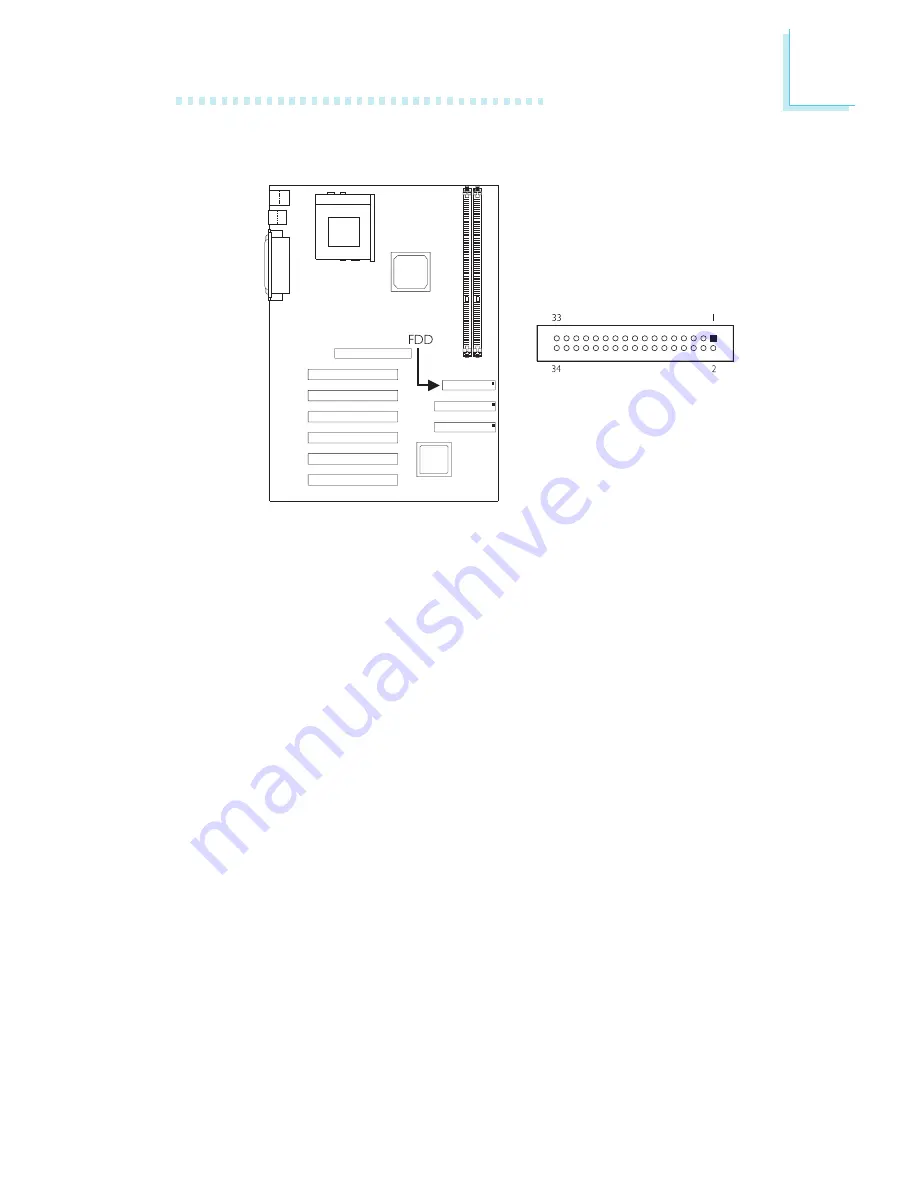
2.7.4  Floppy Disk Drive Connector

The system board is equipped with a shrouded floppy disk drive

connector that supports two standard floppy disk drives. To prevent

improper floppy cable installation, the shrouded floppy disk header

has a keying mechanism. The 34-pin connector on the floppy cable

can be placed into the header only if pin 1 of the connector is

aligned with pin 1 of the header. You may enable or disable this

function in the Integrated Peripherals submenu of the BIOS.

Connecting the Floppy Disk Drive Cable

1. Install the 34-pin header connector of the floppy disk drive cable

into the shrouded floppy disk header (FDD) on the system

board. The colored edge of the ribbon should be aligned with pin

1 of FDD.

2. Install the other 34-pin header connector(s) into the disk drive(s).

Align the colored edge of the daisy chained ribbon cable with pin

1 of the drive edge connector(s). The end-most connector should

be attached to the drive you want to designate as Drive A.

Summary of Contents for AK76-SN

Page 1: ...AK76 SN Rev A System Board User s Manual 46500051...

Page 2: ...revise this publication and make changes to its contents at any time without obligation to notify any person or entity of such revisions or changes 2000 All Rights Reserved Trademarks Microsoft MS DOS...

Page 3: ...ticular installation If this equipment does cause harmful interference to radio or television reception which can be determined by turning the equipment off and on the user is encouraged to try to cor...

Page 4: ...and Connectors Chapter 3 Award BIOS Setup Utility 3 1 The Basic Input Output System 3 1 1 Standard CMOS Features 3 1 2 Advanced BIOS Features 3 1 3 Advanced Chipset Features 3 1 4 Integrated Periphera...

Page 5: ...4 Supported Softwares 4 1 Desktop Management Interface 4 2 Drivers and Utilities Appendix A System Error Messages A 1 POST Beep A 2 Error Messages Appendix B Troubleshooting B 1 Troubleshooting Check...

Page 6: ...processor interface speed DDR Auto detect processor voltage Clock multiplier from 5 0 to 12 5 Supports VID FID Override System Memory Two 184 pin DDR DIMM sockets Uses 64Mbit 128Mbit 256Mbit and 512M...

Page 7: ...to your PC The system board is also equipped with 6 dedicated PCI slots that comply to PCI Local Bus Specification rev 2 2 ATX Double Deck Ports PC 99 color coded connectors Two USB ports Two NS16C550...

Page 8: ...board allows you to connect the optional 3rd and 4th USB ports These optional USB ports which are mounted on a card edge bracket will be provided as an option USB allows data exchange between your co...

Page 9: ...Status section in chapter 3 for more information 1 1 3 Intelligence Over Voltage The Over Voltage function allows you to manually adjust to a higher core voltage that is supplied to the CPU Although...

Page 10: ...t If you are using a modem add in card the 5VSB power source of your power supply must support a minimum of 720mA Wake On LAN The Wake On LAN function allows the network to remotely wake up a Soft Pow...

Page 11: ...tures that enables PCs to implement Power Management and Plug and Play with operating systems that support OS Direct Power Management Virus Protection Most viruses today destroy data stored in hard dr...

Page 12: ...2 12 Hardware Installation 2 1 System Board Layout Chapter 2 Hardware Installation...

Page 13: ...oughout any procedures requiring ESD protection The system board is equipped with two 184 pin DDR DIMM Dual In line Memory Module sockets that support unbuffered or registered DDR SDRAM DIMM Double Da...

Page 14: ...the module aligned with the keys on the socket 3 Seat the module vertically into the socket Make sure it is completely seated The tabs will hold the DIMM in place Pin 1 2 2 1 Installing the DIM Module...

Page 15: ...On On Off Off Off Off 1 On Off On Off On Off On Off 2 On On Off Off On On Off Off 3 Off Off Off Off On On On On 4 Off Off Off Off On On On On CPU Frequency Ratio Select SW1 The table above shows the...

Page 16: ...ttings on pins 1 to 4 will have no effect On Manual use pins 1 2 3 and 4 to select the desired core voltage CPU Core Voltage Select SW2 SW2 allows you to manually adjust the core voltage that is suppl...

Page 17: ...CPU s Front Side Bus CPU Front Side Bus Select Jumpers JP2 JP3 and JP4 Set these jumpers according to the front side bus of the CPU installed on the system board 2 3 On 100MHz 200MHz DDR CPU default...

Page 18: ...m because the CPU s external system bus clock was incorrectly set in the BIOS you can reconfigure the system with the default values stored in the ROM BIOS To load the default values stored in the ROM...

Page 19: ...fter powering on the system press Del to enter the main menu of the BIOS 5 Select the Frequency Voltage Control submenu and press Enter 6 Set the CPU Clock field to its default setting or an appropria...

Page 20: ...N3 and COM 2 CN5 both in Teal Turquoise color located at the ATX double deck ports of the board These ports are RS 232C asynchronous communication ports with 16C550A compatible UARTs that can be used...

Page 21: ...eyboard Purple ports both at location CN1 of the ATX double deck ports of the system board The PS 2 mouse port uses IRQ12 If a mouse is not connected to this port the system will reserve IRQ12 for oth...

Page 22: ...onal mode and at a speed faster than the SPP s data transfer rate Allows bidirectional parallel port op eration at maximum speed 2 7 3 Parallel Port The system board has a standard parallel port CN4 B...

Page 23: ...pin 1 of the header You may enable or disable this function in the Integrated Peripherals submenu of the BIOS Connecting the Floppy Disk Drive Cable 1 Install the 34 pin header connector of the floppy...

Page 24: ...or secondary IDE controller in the Integrated Peripherals submenu of the BIOS Connecting the IDE Disk Drive Cable 1 If you are connecting two IDE drives install the 40 pin connector of the IDE cable...

Page 25: ...A 2 ATA 33 ATA 66 or ATA 100 hard drives We recommend that you use hard drives from the same manufacturer In a few cases drives from two different manufacturers will not function properly when used to...

Page 26: ...2 26 Hardware Installation 2 7 6 Universal Serial Bus Ports USB 2 USB 1 USB 3 and USB 4 Pin 1 2 3 4 5 Function VCC Data Data Ground Ground Function Ground Ground Data Data VCC Pin 6 7 8 9 10...

Page 27: ...ard USB ports CN2 Black are located at the ATX double deck ports of the board The J6 connector on the system board allows you to connect the optional 3rd and 4th USB ports These optional USB ports whi...

Page 28: ...nect your IrDA cable to connector J5 on the system board Set UART 2 Mode in the Integrated Peripherals submenu of the BIOS to the type of IrDA standard supported by your device You must have the prope...

Page 29: ...r Pin 1 2 3 Function Ground 12V Sense The CPU must be kept cool by using a fan with heatsink Connect the CPU fan to the 3 pin fan connector at location J1 white connector on the system board The syste...

Page 30: ...unction Ground 12V N C If you are installing a second CPU fan in the system unit connect the fan s connector to location J9 red connector on the system board The system is not capable of monitoring th...

Page 31: ...em board is equipped with two chassis fan connectors Installing chassis fans will provide adequate airflow throughout the chassis to prevent overheating the CPU The system is capable of monitoring the...

Page 32: ...Hardware Installation 2 7 11 Chip Fan Connector Pin 1 2 Function 12V Ground The AMD 761 chip must be kept cool by using a fan with heatsink Connect the fan s connector to location J2 on the system bo...

Page 33: ...pt To use the Wake On LAN function you must enable the RI Resume field in the Power Management Setup of the BIOS Your LAN card package should include a cable Connect one end of the cable to the wakeup...

Page 34: ...ugh the internal modem card To use this function connect one end of the cable that came with the card to the card s wake on ring connector and the other end to location J3 on the system board You must...

Page 35: ...power connector is shown below Pin 1 2 3 4 5 6 7 8 9 10 Function 3 3V 3 3V Ground 5V Ground 5V Ground PW OK 5VSB 12V Pin 11 12 13 14 15 16 17 18 19 20 Function 3 3V 12V Ground PS ON Ground Ground Gro...

Page 36: ...Connector This connects to the speaker installed in the system chassis SP SW ATX Power Switch Depending on the setting in the BIOS setup this switch is a dual function power button that will allow you...

Page 37: ...Green Signal Green LED Power N C Speaker Signal N C Ground Speaker Power PWRBT Signal Ground N C SMI Signal Ground N C N C H W Reset Ground N C LED Power N C Ground P LED Power Standby LED When the s...

Page 38: ...een Press DEL to enter setup If the message disappears before you respond restart the system or press the Reset button You may also restart the system by pressing the Ctrl Alt and Del keys simultaneou...

Page 39: ...hen press Enter 3 1 1 Standard CMOS Features Use the arrow keys to highlight Standard CMOS Features and press Enter A screen similar to the one on the next page will appear The settings on the screen...

Page 40: ...manual or Help desk on which one to select Capacity Displays the approximate capacity of the disk drive Usually the size is slightly greater than the size of a formatted disk given by a disk checking...

Page 41: ...board The system boot will not stop for a keyboard error it will stop for all other errors All But Diskette The system boot will not stop for a disk error it will stop for all other errors All But Dis...

Page 42: ...Features Item Help Menu Level Allows you to choose the VIRUS warning feature for IDE Hard Disk boot sector protection If this function is enabled and someone attempt to write data into this area BIOS...

Page 43: ...t Device and Third Boot Device fields respectively The BIOS will boot the operating system according to the sequence of the drive selected The options are Floppy LS ZIP HDD 0 SCSI CDROM HDD 1 HDD 2 HD...

Page 44: ...egin to repeat Security Option This field determines when the system will prompt for the password everytime the system boots or only when you enter the BIOS setup Set the password in the Set Superviso...

Page 45: ...Note that some graphics boards require that this option be disabled The default value is Enabled Enabled Video shadow is enabled Disabled Video shadow is disabled C8000 CBFFF Shadow to DC000 DFFFF Sh...

Page 46: ...be cacheable thus providing better video performance If your graphics card does not support this function set this field to Disabled 3 1 3 Advanced Chipset Features CMOS Setup Utility Copyright C 1984...

Page 47: ...re Size MB This field is relevant to the memory mapped graphics data of the AGP card installed in your system The options are 32MB 64MB 128MB and 256MB Leave this field in its default setting which is...

Page 48: ...r are dependent on the system design Slower rates may be required in certain system designs to support loose layout or slower memory When this field is set to Auto the system will automatically set th...

Page 49: ...nimum bank active time time from active to precharge in the same bank SDRAM CAS Latency This field is used to specify the DRAM CAS latency SDRAM Trcd Timing Value This field is used to specify the del...

Page 50: ...his manual In the actual CMOS setup you have to use the scroll bar to view the fields The settings on the screen are for reference only Your version may not be identical to this one CMOS Setup Utility...

Page 51: ...your hard drive or CD ROM Auto The BIOS will automatically detect the settings for you Disabled The BIOS will not detect these categories Init Display First This field is used to select whether to in...

Page 52: ...n manually configure the serial ports by selecting 3F8 IRQ4 2F8 IRQ3 3E8 IRQ4 2E8 IRQ3 or Disabled UART 2 Mode The system board supports IrDA function for wireless connectivity between your computer a...

Page 53: ...for the best option Normal Allows normal speed operation but in one direction only ECP Extended Capabilities Port Allows parallel port to operate in bidirectional mode and at a speed faster than the...

Page 54: ...this manual In the actual CMOS setup you have to use the scroll bar to view the fields The settings on the screen are for reference only Your version may not be identical to this one CMOS Setup Utili...

Page 55: ...orts it Standby Mode This is selectable only when the Power Management field is set to User Define When the system enters the Standby mode according to the power saving time selected video will be shu...

Page 56: ...ure the system s power is off You must press the Power button to power on the system On When power returns after an AC power failure the system will automatically power on Former Sts When power return...

Page 57: ...ter 2 for more information Modem USE IRQ This field allows you to select an IRQ for your medem The options are 3 4 5 7 9 10 11 and NA RTC Resume Enabled When Enabled you can set the date and time you...

Page 58: ...ar When enabled access to the specified IRQ will cause the system to wake up completely from the power management mode When disabled the system will not wake up from the power management mode despite...

Page 59: ...rs some very technical items and it is strongly recommended that only experienced users should make any changes to the default settings The settings on the screen are for reference only Your version m...

Page 60: ...t with the original PC AT bus specification PCI VGA Palette Snoop This field determines whether the MPEG ISA VESA VGA cards can work with PCI VGA or not The default value is Disabled Enabled MPEG ISA...

Page 61: ...for the USB device connected to your system However if you are not using USB devices and an ISA slot requires an IRQ set this field to Disabled The IRQ previously occupied by the USB device will be a...

Page 62: ...12V These fields show the output voltage of the power supply 3 1 7 PC Health Status The settings on the screen are for reference only Your version may not be identical to this one CMOS Setup Utility...

Page 63: ...speed of the DIMMs installed on the system board Spread Spectrum Leave this field in its default setting Do not alter this setting unless advised by an engineer or technician CPU Clock This field prov...

Page 64: ...s option in the main menu and press Enter The message below will appear Load Fail Safe Defaults Y N N If you want to proceed type Y and press Enter The default settings will be loaded 3 1 10 Load Opti...

Page 65: ...in exactly the same password If you type in a wrong password you will be prompted to enter the correct password again To delete or disable the password function highlight Set Supervisor Password and p...

Page 66: ...tics on the screen If you wish to make additional changes to the setup press Ctrl Alt Esc simultaneously or Del after memory testing is done 3 1 14 Exit Without Saving When you do not want to save the...

Page 67: ...umbers of hardware installed etc are automatically detected and stored in the DMI pool which is a part of the system board s Plug and Play BIOS Additional information such as ISA based peripherals whi...

Page 68: ...e or arrow keys then press Enter 3 The cursor will move to the screen you select allowing you to edit information The screen will also display the auto detected information 4 Press F10 to update the e...

Page 69: ...or arrow keys to select the Load DMI File menu 2 The following message will appear Press Enter to select DMI file for load Press Enter 3 The DMI files will appear on the screen Select the file you wo...

Page 70: ...ME Windows 2000 and Windows NT 4 0 operating systems If after inserting the CD Autorun did not automatically start which is the Main Board Utility CD screen did not appear please go directly to the ro...

Page 71: ...e consists of a single long beep A 2 Error Messages One or more of the following messages may be displayed if the BIOS detects an error during the POST This list indicates the error messages for all A...

Page 72: ...fixed disk Hard Disk s fail 08 Sector Verify failed Keyboard is locked out Unlock the key The BIOS detects that the keyboard is locked Keyboard controller is pulled low Keyboard error or no keyboard...

Page 73: ...st the outlet by plugging in a lamp or other electrical device 4 The monitor is turned on 5 The display s brightness and contrast controls are adjusted properly 6 All add in boards in the expansion sl...

Page 74: ...ing happens 1 Check that one end of the AC power cord is plugged into a live outlet and the other end properly plugged into the back of the system 2 Make sure that the voltage selection switch on the...

Page 75: ...a cable connection problem However if your hard drive has a large capacity it will take a longer time to format Parallel Port The parallel printer doesn t respond when you try to print 1 Make sure tha...

Page 76: ...nfigured correctly Keyboard Nothing happens when a key on the keyboard was pressed 1 Make sure the keyboard is properly connected 2 Make sure there are no objects resting on the keyboard and that no k...

Reviews: