background image


However 1/4 in. (6 mm) clearance should be allowed in case the dryer 
needs moving. 


C.  A 10 in. (250 mm) clearance is required from top at all other points. 

VI. Floor 

This unit may be installed upon a combustible floor. 

 
Do not obstruct the flow of combustion and ventilation air. 
 
Maintain minimum of 1 in. (25 mm) clearance between duct and combustible material. 
 
Refer to the installation label attached to the Belt Guard on the rear of the dryer for other 
installation information and start-up instructions. 


3.  

MAKE-UP AIR

.  Adequate make-up air (600CFM/DRUM (17 m

3

/min.), 

1200CFM/DRYER (34 m

3

/min)) must be supplied to replace the air exhausted by dryers on all 

types of installations.  Provide a minimum of 1.5 ft² (0.14 m²) make-up air opening to the outside 
for each dryer.  This is a net requirement of effective area.   Screens, grills or louvers, which will 
restrict the flow of air, must be considered.  Consult the supplier to determine the free area 
equivalent for the grill being used. 
 

The source of make-up air should be located sufficiently away from the dryers to allow an 

even airflow to the air intakes of all dryers.  Multiple openings should be provided. 
 

 NOTE:

 The following considerations must be observed for gas dryer installations where dry 

cleaners are installed. The sources of all make-up air and room ventilation air movement to all 
dryers must be located away from any dry cleaners.  This is necessary so that solvent vapours 
will not be drawn into the dryer inlet ducts.  Dry cleaner solvent vapours will decompose in 

Summary of Contents for DDAD30HC-59 Series Dryers

Page 1: ... the user smells gas Consult your local gas supplier for procedure to be followed if the odour of gas is present Post the following For Your Safety caution in a prominent location FOR YOUR SAFETY Do not store or use gasoline or other flammable vapours or liquids in the vicinity of this or any other appliance FOR YOUR SAFETY THIS MACHINE IS FOR DRYING ONLY FABRICS CLEANED IN WATER To avoid possibil...

Page 2: ...rammed data is protected from power interruptions of any length and the customer s individual cycle is protected up to 3 seconds This is done without batteries LEAVE THE ELECTRICAL POWER TO THE DRYER ON AT ALL TIMES except when necessary for service or other similar activities The hour meter function adds only full hours to its reading If the power is shut off every night any fraction of an hour o...

Page 3: ...3 Figure 1 30 Stack Dryer Dimensions inches mm ...

Page 4: ...e edge of the dryer Thread two leveling legs about two thirds into the T nuts on the base from which the crating bolts were removed Remove the block from under the dryer With a walking motion move the dryer completely off the crate base Discard the crate base Tip the dryer sidewise as previously done and place the block under the edge of the dryer on the raised side Thread the leveling legs into t...

Page 5: ...installations Provide a minimum of 1 5 ft 0 14 m make up air opening to the outside for each dryer This is a net requirement of effective area Screens grills or louvers which will restrict the flow of air must be considered Consult the supplier to determine the free area equivalent for the grill being used The source of make up air should be located sufficiently away from the dryers to allow an ev...

Page 6: ... Electrical Requirements of the country of installation Individual 20A circuit breakers for each dryer are required The installer must provide a disconnect switch which will interrupt both lines It may be a local or national requirement to provide an electrical interruption switch visible and accessible from the room in which the dryer is installed The wiring diagram is located in the control box ...

Page 7: ...lution Never check with an open flame Note There are two 9 mm pressure taps one at the inlet side one at the outlet side of the gas valve for use if it is necessary to check either pressure PRESSURE REGULATOR ADJUSTMENT Adjustments should be made by qualified personnel only 1 With dryer off unscrew the outlet pressure tap on the gas control valve a half turn and slip pressure gauge tube over nippl...

Page 8: ... of installation can cause slow drying time excessive heat and lint in the room From an operational standpoint incorrect or inadequate exhausting can cause a cycling of the high limit thermostat which shuts off the main burners and results in inefficient drying The oval exhaust duct connection near the top of the dryer will accept a compressed 8 round duct Individual exhausting of the dryers is re...

Page 9: ... the entry of a ball of 16 mm in diameter while the machine is not operating but will allow entry of a ball 6 mm in diameter while operating When exhausting a dryer straight up through a roof the overall length of the duct has the same limits as exhausting through a wall A rain cap must be placed on top of the exhaust and must be of such a type as to be free from clogging The type using a cone sha...

Page 10: ...10 DRYER SHUTDOWN To render the dryer inoperative turn off the main gas shut off valve and disconnect power to the dryer ...

Page 11: ...11 ...

Page 12: ...is connected to sensor input LOAd appears on the 4 digit display and the remaining dry time is reset F3 EEPROM corrupted Dryer will not start and F3 appears on the 4 digit display The power to the dryer must be cycled to reset the controller Fault should only occur when starting a dry cycle F4 Gas valve on fault The drying temperature did not increase 1º F in 15 minutes F4 will flash on the displa...

Page 13: ...the STOP button is pressed once or the door is opened during an operating cycle SWITCHES Pushbuttons Description This touch pad switch will increment increase dry time cool down time and drying temperature It will also scroll upwards when Up Increase selecting a dry cycle This touch pad switch will decrement decrease dry time cool down time and drying temperature It will also scroll downwards Down...

Page 14: ...eleased twice donE This message blinks immediately after completion of the dry cycle and continues to blink until the stop key on the dryer controller touch pad is pressed or the dryer loading door is opened Prog This message is displayed when entering the permanent programming mode 15 This message appears while the dryer is in the heating time of a dry cycle The decimal point will blink if the ou...

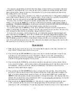
Page 15: ...your untangled load into the dryer cylinder and close the dryer loading door Notice that the dryer controller 4 digit numerical display should show the word LOAd If it does not show this word then press and release the STOP touch pad key on the dryer controller twice 2 Press and release the UP or DOWN arrow touch pad key on the dryer controller to select a dry cycle 3 Once the desired dry cycle is...

Page 16: ...y shows and operates in the Fahrenheit or Celsius mode This jumper is labeled as TEMP SELECT and has three pins The back and middle pins are for Celsius and the front and middle pins are for Fahrenheit which is indicated by the letter C for Celsius and the letter F for Fahrenheit The other jumper located at the back middle side of each circuit board controls is used for choosing either a reversing...

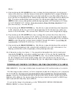
Page 17: ...splay and allow you to start the temporary dry cycle If you start the temporary dry cycle the 4 digit numerical display will change to the total dry time and count down to 0 as the dry cycle progresses PROCEDURE 1 Make sure the dryer is not in a dry cycle The 4 digit numeric display on the dryer controller will show LOAd when the dryer is not in a dry cycle 2 Press and release the UP or DOWN arrow...

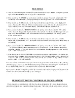
Page 18: ...h 60 minutes To not change the cool down time do not press the arrow keys Go to the next step 9 Press and release the SELECT ENTER key Once this key is pressed and released the cool down L E D and the programming L E D will switch off and the dry cycle L E D will remain on The flashing cool down time on the 4 digit display will stop flashing and remain 10 At this point you have two choices 1 You c...

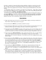
Page 19: ...y five degrees 6 Now press and release the SELECT ENTER touch pad key on the dryer controller The number 185 will stop flashing and the temperature L E D will switch off The dryer control display will now show a number 5 the cool down L E D will illuminate and the programming L E D and dry cycle 1 L E D will remain on 7 Press and release the SELECT ENTER key on the dryer controller touch pad since...

Page 20: ...y cycle L E D will illuminate to indicate which dry cycle you are choosing If you press either arrow key and hold it down the controller will sequence through the five dry cycles 5 Press and release the SELECT ENTER key once you have chosen the dry cycle you want to change After you press this key the dry time L E D will illuminate The dry cycle L E D and the programming L E D will remain illumina...

Page 21: ...D will remain on and the 4 digit numeric display will change to Prog 12 Press and release the STOP key to save the cycle program and escape the programming mode If you want to change the same dry cycle program again press the SELECT ENTER key and continue at step 6 of this procedure If you want to modify another dry cycle program go to step 4 of this procedure and continue 13 If you pressed the ST...

Page 22: ...ad key three times until the dryer controller display shows the number 195 8 Press and release the SELECT ENTER touch pad key The dry time L E D and the programming L E D will remain on and the temperature L E D will switch off The cool down L E D will illuminate and the dryer controller display will show the number 5 9 Press and release the DOWN arrow touch pad key twice until the dryer controlle...

Page 23: ... can result in lint accumulation and reduced ventilation of exhaust gases MONTHLY 1 Removal of accumulated lint using a brush and vacuum cleaner Disconnect power to dryer before beginning a Clean lint from lint screen compartments b Remove lint accumulation from end bells of motors c Vacuum the openings in the burner primary air openings d Remove any lint from control compartment e Remove lint and...

Page 24: ...dislodged lint from drying chamber Failure to do so can result in the risk of fire ANNUALLY 1 Check intermediate pulley bearings for wear 2 Check and remove any lint accumulation from exhaust system Lint accumulation causes reduced drying performance reduced ventilation of exhaust gases and an increased risk of fire SERVICE PARTS PART NUMBER DRIVE BELT MOTOR 9040 077 001 DRIVE BELT TUMBLER 9040 07...

Reviews: