E N G L I S H
8
NOTE:
Metal or hardwoods should never be cut in
orbital action.
TO ADJUST THE CUTTING ACTION
1. Move the cutting action lever (i) between the
four cutting positions: 0, 1, 2, and 3.
2. Position 0 is straight cutting.
3. Positions 1, 2, and 3 are orbital cutting.
The aggressiveness of the cut increases as the lever
is adjusted from one to three, with three being the
most aggressive cut.
LED Light
The jig saw is equipped with a light which projects
on the cutting path.
The light will come on when the trigger switch is
depressed and will go off when the trigger switch is
released.
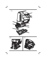
Removable Shoe Sleeve (fi g. 6)
The non-marring shoe sleeve (e) should be used
when cutting surfaces that scratch easily, such as
laminate, veneer, or paint. It can also be used to
protect the shoe surface during transportation and
storage.
To attach shoe sleeve, place the front of the shoe (f)
into the front of the shoe sleeve (e) and lower the jig
saw as shown in figure 6. The shoe sleeve will click
securely onto the rear of the shoe.
To remove shoe sleeve, grasp the sleeve from the
bottom at the two rear tabs and pull down and away
from the shoe
Hints for Optimum Use
SAWING LAMINATES
As the saw blade cuts on the upward stroke,
splintering may occur on the surface closest to the
shoe plate.
•
Use a fine-tooth saw blade.
•
Saw from the back surface of the workpiece.
•
To minimize splintering, clamp a piece of
scrap wood or hardboard to both sides of the
workpiece and saw through this sandwich.
SAWING METAL
•
Be aware that sawing metal takes much more
time than sawing wood.
•
Use a saw blade suitable for sawing metal.
•
When cutting thin metal, clamp a piece of scrap
wood to the back surface of the workpiece and
cut through this sandwich.
•
Spread a film of oil along the intended line of cut
for easier operation and longer blade life. For
cutting aluminum, kerosene is preferred.
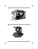
Rip/Circle Cutting (fi g. 7, 8)
Ripping and circle cutting without a pencil line are
easily done with the rip fence / circle guide (not
included; available at extra cost).
Using the screw supplied with the accessory guide,
position as shown in figure 7 and thread the screw
into the shoe to clamp the fence securely.
When ripping, position as shown in figure 7 and slide
the rip fence under the screw from either side of the
saw. Set the cross bar (j) at desired distance from
blade and tighten screw. For ripping, the cross bar
should be down and against the straight edge of the
workpiece as shown.
When circle cutting, adjust rip fence so that distance
from blade to hole in fence arm (k) is at the desired
radius and tighten screw. Place saw so that hole
in fence arm is over center of circle to be cut (drill
hole for blade or cut inward from edge of material
to get blade into position). When saw is properly
positioned, drive a small nail through hole in fence
arm. Using rip fence as a pivot arm, begin cutting
circle. For circle cutting, the cross bar should be up,
as shown in figure 8.
MAINTENANCE
Your D
E
WALT power tool has been designed to
operate over a long period of time with a minimum
of maintenance. Continuous satisfactory operation
depends upon proper tool care and regular cleaning.
• Regularly clean the ventilation slots in your tool
using a soft brush or dry cloth.
• Regularly clean the motor housing using a
damp cloth. Do not use any abrasive or solvent-
based cleaner.
Lubrication
Your power tool requires no additional lubrication.
Cleaning
WARNING:
Blow dirt and dust out of
the main housing with dry air as often as
dirt is seen collecting in and around the
Summary of Contents for DW349
Page 1: ...DW349 ...
Page 3: ...1 Figure 1 1 ﺷﻛﻝ Figure 2 2 ﺷﻛﻝ Figure 3 3 ﺷﻛﻝ a b c j h d f g i e g f ...
Page 4: ...2 Figure 4 4 ﺷﻛﻝ Figure 6 6 ﺷﻛﻝ Figure 5 5 ﺷﻛﻝ h f e ...
Page 5: ...3 Figure 7 7 ﺷﻛﻝ Figure 8 8 ﺷﻛﻝ k ...
Page 19: ... ﺍﻟﻌﺭﺑﻳﺔ 17 ...
Page 20: ... ﺍﻟﻌﺭﺑﻳﺔ 18 ...
Page 21: ... ﺍﻟﻌﺭﺑﻳﺔ 19 ...
Page 22: ... ﺍﻟﻌﺭﺑﻳﺔ 20 ...
Page 23: ... ﺍﻟﻌﺭﺑﻳﺔ 21 ...
Page 24: ... ﺍﻟﻌﺭﺑﻳﺔ 22 ...
Page 25: ... ﺍﻟﻌﺭﺑﻳﺔ 23 ...
Page 26: ...90617791 03 15 ...


