English
10
D
e
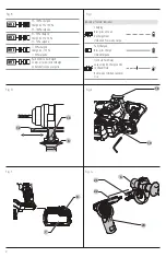
WALT Tool Tag Ready (Fig. A)
Optional Accessory
Your tool comes with mounting holes
15
and fasteners for
installing a
D
e
WALT
Tool Tag. You will need a T20 bit tip to
install the tag. Only use the screws provided. The
D
e
WALT
Tool Tag is designed for tracking and locating professional
power tools, equipment, and machines using the
D
e
WALT
Tool Connect™ app. For proper installation and use of the
D
e
WALT
Tool Tag refer to the
D
e
WALT
Tool Tag manual.
SHOCKS® Active Vibration Control
System
For best vibration control, hold the tool as described in
Proper Hand Position
and apply just enough pressure so the
damping device on the main handle is approximately mid
stroke. The hammer only needs enough pressure to engage
the active vibration control. Applying too much pressure will
not make the tool actuate faster and active vibration control
will not engage.
E-Clutch® System (Fig. I)
In addition to the integral (mechanical) clutch, the
D
e
WALT
anti‑rotation E‑Clutch® system, offers technology capable
of detecting the motion of the tool. This feature senses
the motion of the tool and shuts it down if necessary. The
E‑Clutch
®
indicator LED
16
illuminates when the E‑Clutch®
System is engaged.
Your rotary hammer has an E‑Clutch
®
indicator LED
16
,
indicating the E‑Clutch® (ADC) function. Refer to the table for
more information on LED functionality.
Indicator
Diagnosis
Solution
OFF
Tool is
functioning
normally
Follow all warnings and instructions
when operating the tool.
SOLID
E‑Clutch
®
System
has been
activated
(ENGAGED)
With the tool properly supported,
release trigger. The tool will
function normally when the trigger
is depressed again and the indicator
light will go out
WARNING:
Drill may stall if overloaded causing a
sudden twist. Always expect the stall. Grip the drill
firmly to control the twisting action and avoid injury.
Proper hand position requires one hand on the main
handle
9
, with the other hand on the side handle
6
.
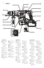
Proper Hand Position (Fig. A, K)
WARNING:
To reduce the risk of serious personal injury,
ALWAYS
use proper hand position as shown.
WARNING:
To reduce the risk of serious personal
injury,
ALWAYS
hold securely in anticipation of a
sudden reaction.
into the handle until the battery pack is firmly seated in the
tool and ensure that it does not disengage.
To remove the battery pack from the tool, press the release
button
8
and firmly pull the battery pack out of the tool
handle. Insert it into the charger as described in the charger
section of this manual.
OPERATION
WARNING: To reduce the risk of serious personal
injury, turn unit off and remove the battery pack
before making any adjustments or removing/
installing attachments or accessories.
An
accidental start‑up can cause injury.
Wireless Tool Control (Fig. A)
CAUTION:
Read all saftey warnings, instruction and
specifications of the appliance which is paired with
the tool.
Your tool is equipped with a Wireless Tool Control transmitter
which allows your tool to be wirelessly paired with another
Wireless Tool Control device, such as a
D
e
WALT
dust extractor.
To pair your tool using Wireless Tool Control, depress the
trigger switch
1
and the Wireless Tool Control pairing button
on the seperate device. An LED on the seperate device will let
you know when your tool has been successfully paired.
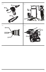
DWH200D Dust Extraction System
(Fig. H)
Your heavy‑duty cordless rotary hammer comes with an
adapter for the DWH200D dust extraction system.
The standard SDS Plus tool holder adapter (short) comes
attached in the DWH200D. Your tool requires the included
longer holder adapter.
1. Remove the cross head screw
25
from the short
adapter
21
using a cross head screwdriver (Fig. H).
2. Then use the screw
25
to assemble the long tool holder
adapter
22
to the dust brush body
20
. Tighten securely.
3. Slide the newly assembled dust brush
20
and tool
holder adapter
22
into the slot
23
on the top of the
side handle assembly
6
until you hear an audible click.
4. Connect dust extractor
24
to the dust brush
assembly
20
(Fig. H).
To Install the Belt Hook
1. Insert the hook into one of the slots, on left or right side,
below the main handle.
2. Install the screw on the underside of the main handle. Be
sure to securely tighten the screw.
To Remove or Move the Belt Hook
1. Remove the screw located on the underside of the
main handle.
2. Pull the belt hook away from the main handle.
3. Insert the hook into one of the slots, on left or right
side, below the main handle, or install the screw on the
underside of the main handle. Be sure to securely tighten
the screw.
Installing and Removing the Battery Pack
(Fig. F)
nOTE:
For best results, make sure your battery pack is
fully charged.
To install the battery pack
7
into the tool handle, align the
battery pack with the rails inside the tool’s handle and slide it
Summary of Contents for DCH416
Page 5: ...3 Fig H 16 Fig I Fig J Fig K 10 6 9 11 20 22 21 25 ...
Page 39: ...37 ...


