


Hardware ports, switches and LEDs
Deutschmann Automation GmbH & Co. KG
28
UNIGATE Fieldbus Gateway UNIGATE CL - Powerlink V. 1.8
17.6.10
12.3.3
LED "Link / Activity 2"
This LED is directly controlled by the Powerlink processor and shines when the Gateway is loca-
ted at the RJ45 (2) at a working net (link pulses are received) and flickers during network data
traffic (Activity).
12.3.4
LED "State / Error"
12.3.5
LED "Power"
This LED is connected directly to the (optionally also electrically isolated) supply voltage of the
serial interface (RS232/422/485).
12.3.6
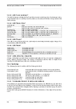
LED "State"
12.3.7
LEDs (Error No. / Select ID)
If these 4 LEDs flash and LED “State“ simultaneously lights red, the error number is displayed in
binary notation (conversion table, see Annex) in accordance with the table in chapter "Error
handling". Additionally these LEDs are controllable via Script:
12.4 Switches
The Gateway features 6 switches with the following functions:
Termination Rx 422
switchable Rx 422-terminating resistor for the serial interface
Termination Tx 422
switchable Tx 422- or RS485-terminating resistor for the serial
interface
Rotary coding switch S4
ID High for serial interface i. e. configmode
Rotary coding switch S5
ID Low for serial interface i. e. configmode
Rotary coding switch High
Powerlink Node ID (High byte)
Rotary coding switch Low
Powerlink Node ID (Low byte)
12.4.1
Termination Rx 422 + Tx 422 (serial interface)
If the Gateway is operated as the physically first or last device in an RS485-bus or as 422, there
must be a bus termination at this Gateway. In order to do this the termination switch is set to posi-
tion ON. The resistor (150
Ω
) integrated in the Gateway is activated. In all other cases, the switch
remains in position OFF.
Please refer to the general RS485 literature for further information on the subject of bus termina-
tions.
STATUS LED
State
LED off
NMT_GS_OFF, NMT_GS_INITIALISATION,
NMT_CS_NOT_ACTIVE / NMT_MS_NOT_ACTIVE
LED flickering
NMT_CS_BASIC_ETHERNET
LED single flash
NMT_CS_PRE_OPERATIONAL_1 / NMT_MS_PRE_OPERATIONAL_1
LED double flash
NMT_CS_PRE_OPERATIONAL_2 / NMT_MS_PRE_OPERATIONAL_2
LED triple flash
NMT_CS_READY_TO_OPERATE / NMT_MS_READY_TO_OPERATE
LED on
NMT_CS_OPERATIONAL / NMT_MS_OPERATIONAL
LED blinking
NMT_CS_STOPPED
Lights green
Controllable via Script
Flashes green
Controllable via Script
Flashes green/red
Controllable via Script
Lights red
General Gateway error (see LEDs Error No.), controllable via Script
Flashes red
UNIGATE is in the configuration / test mode, controllable via Script
Summary of Contents for UNIGATE CL - Powerlink
Page 2: ......


