26.8.11
UNIGATE Fieldbus Gateway CANopen® - ProfibusDP V. 2.3
13
Deutschmann Automation GmbH & Co. KG
Mode of operation of the system
Settings
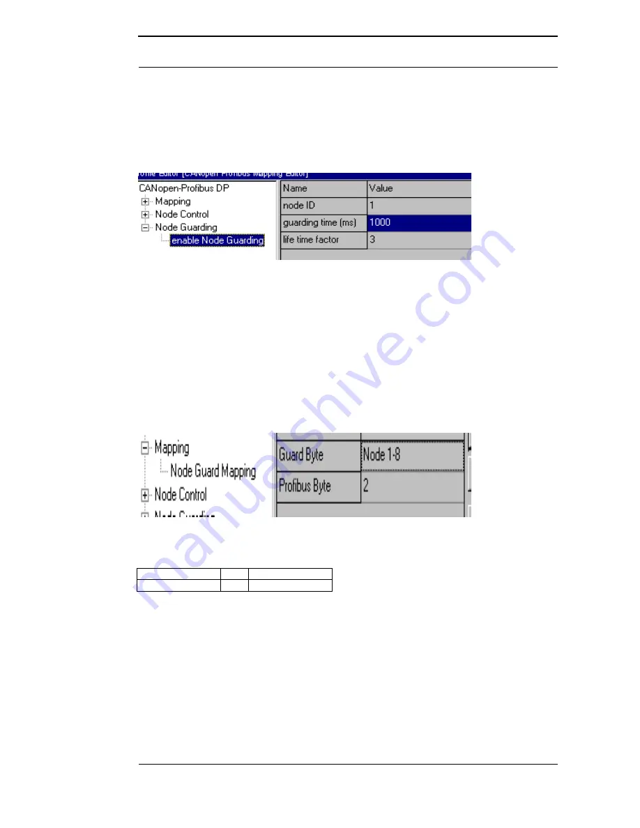
As presetting it applies tfor all slaves that no node guarding is carried out. Shall that node guar-
ding be activated for a slave, an entry "enable node guarding" has to be added to the current
WINGATE configuration. The parameters "node ID", "guarding time" and "life time factor" are to
be determined in every entry.
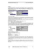
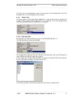
Settings to node guarding
The parameter node ID indicates the ID of the CANopen® node on which the control is supposed
to happen. With the guarding time the interval in which the the master calls on the slave to send
its guarding answer is to be indicated in milliseconds.
The life time factor states how often the answer of the slave may be missing before the master
assumes a failure of the slave.
These settings are available from Gateway software-revision 1.1 on.
4.3.3
Displaying the node guarding states
The node guard mapping is used to represent the node guard states of the single slaves to the
Profibus. Always 8 slaves are represented in one byte; so exactly one bit of information is reser-
ved for one. This information can be shown in any desired spot in the Profibus data of the Gate-
way. So they are shown in the input area of the Profibus master for this Gateway.
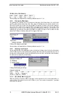
Display of the node guarding information
Arrangement of the bits for the nodes 1- 8:
Node 1-8
Byte MSB ( bit 7)
...
LSB (bit 0)
SlavenNode ID 8
...
Slave node ID 1
If no node guard is activated for a slave, the slave went down or still no node guarding informa-
tion was exchanged, the corresponding bit for this slave is 0. The bit is 1, if node guarding was
activated for this slave and the slave answered in the corresponding time period to the node
guarding inquiries.
Example: For node 1 and 2 node guarding is activated. Slave 1 doesn not answer to the node
guarding and slave ID 2 works regularly. A mapping of information is entered into the Profibus in
the 2nd byte.


