background image

Mode of operation of the system 

Deutschmann Automation GmbH & Co. KG

12

UNIGATE Fieldbus Gateway CANopen® - ProfibusDP  V. 2.3

26.8.11

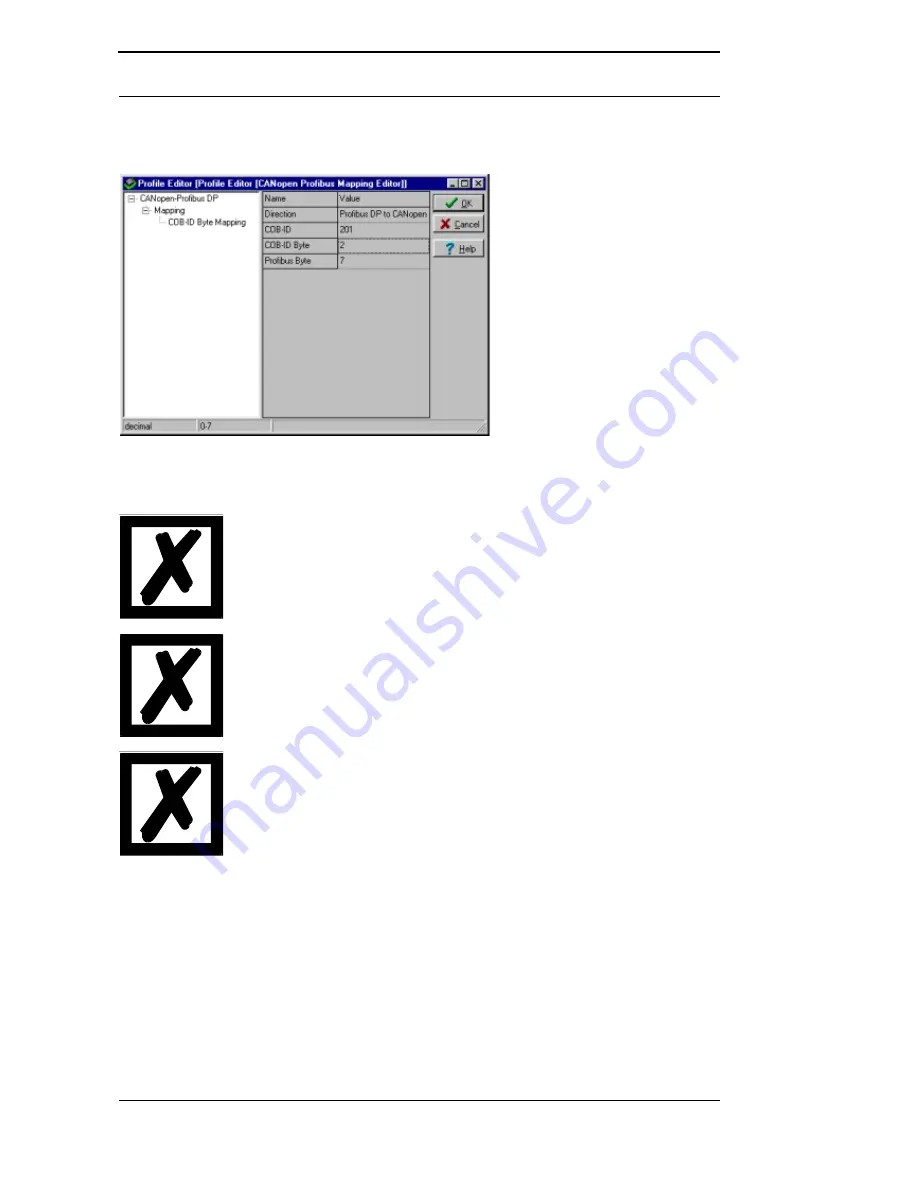
Now the Mappings can be changed, deleted or new ones can be added. Afterwards you only 
have to download the data to the Gateway (menu file\download) and UNIGATE works with the 
new configuration.

It is allowed to map the same byte of a PDO several times to different 
positions in the Profibus.
However, a maximum of 8 mappings per PDO may be entered!

At the mapping from Profibus to CANopen® several mappings can be 
configured for each Profibus-byte. There the total number of these mul-
tiple mappings must not exceed 127.

If possible for the PDO-mappings only COB-IDs from the range 
181H..580H should be used (see DS301-specification for CANopen®). 
Otherwise it might result in crossovers with COB-IDs that CANopen® 
uses for other tasks (SDO-messages, emergency-messages and so on).

4.3.2

Node guarding

If a CANopen® slave controlled by node guarding, it cyclically receives the node guard request 
to answer the inquiry through the CANopen® master. The slave for his part answers this node 
guarding inquiry with the corresponding answer. That way, both master and slave can control 
themselves mutually.
If the slave receives no node guard inquiry it assumes that the bus connection is broken or the 
master went down.

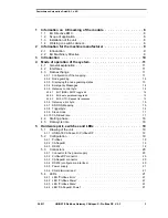
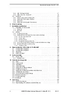
Summary of Contents for UNIGATE CANopen-ProfibusDP

Page 1: ...eway UNIGATE CANopen Master ProfibusDP Slave Article no V2856E Deutschmann Automation GmbH Co KG Carl Zeiss Str 8 D 65520 Bad Camberg Tel 49 0 6434 9433 0 Hotline 49 0 6434 9433 33 Fax 49 0 6434 9433 40 Internet http www deutschmann de ...

Page 2: ......

Page 3: ...Gateway control byte 14 4 3 5 1 Bit 7 MSB EMCY toggle bit 14 4 3 5 2 Bit 6 set operational toggle bit 15 4 3 5 3 Bit 5 RTR Request to response 15 4 3 6 Gateway error byte 15 4 3 7 SDO Obj Mapping 15 4 3 8 Triggerbyte 16 4 3 9 Slave mode 17 4 3 10 CAN Baud rate 17 4 4 Starting phase 18 4 5 Data cycle time 18 5 Hardware ports switches and LEDs 19 5 1 Drawing of the unit 19 5 1 1 UNIGATE CANopen Prof...

Page 4: ...quipotential bonding connection 25 7 2 3 Line routing shield and measures to combat interference voltage 25 7 2 4 General information on line routing 25 7 2 4 1 Shielding of lines 26 8 Representation of the data in ProfibusDP 28 8 1 Configuration telegram 28 8 2 Configuration telegram 28 8 3 Diagnosis 29 8 4 Data exchange 31 9 Technical data 32 9 1 Device data 32 9 1 1 Interface data 34 10 Commiss...

Page 5: ...26 8 11 UNIGATE Fieldbus Gateway CANopen ProfibusDP V 2 3 5 Deutschmann Automation GmbH Co KG 12 Annex 38 12 1 Hexadecimal table 38 13 EG Certificate of Conformance 39 ...

Page 6: ...Deutschmann Automation GmbH Co KG 6 UNIGATE Fieldbus Gateway CANopen ProfibusDP V 2 3 26 8 11 ...

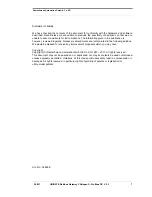
Page 7: ...publication is however reviewed regularly Necessary amendments are incorporated in the following editions We would be pleased to receive any improvement proposals which you may have Copyright Copyright C Deutschmann Automation GmbH Co KG 1997 2011 All rights reserved This document may not be passed on nor duplicated nor may its contents be used or disclosed unless expressly permitted Violations of...

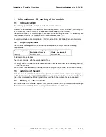
Page 8: ...nd comply with the following requirements Scope of application Requirement applicable to Emitted interference Interference immunity Industry EN 55011 Kl A EN 61000 6 2 Note installation guidelines The module complies with the requirements if you 1 comply with the installation guidelines described in the User Manual when installing and ope rating the module 2 also follow the rules below on installa...

Page 9: ...ve Consequently the module does not have a Declaration of Conformity in relation to the EU Machinery Directive 2 2 EU Machinery Directive The EU Machinery Directive stipulates the requirements applicable to a machine The term machine is taken to mean a totality of connected parts or fixtures see also EN 292 1 Para graph 3 1 The module is a part of the electrical equipment of the machine and must t...

Page 10: ...rofibusDP side it operates as slave and on the CANopen side it operates as master Through a mapping that can be configured the user is in the position to prescribe how CANo pen data are to be imaged in the Profibus and also the other way round The module essentially consists of the following hardware components Electrically isolated interface to the ProfibusDP and to CANopen Profibus ASIC CAN Cont...

Page 11: ...ant CANopen interface and a Profibus interface available as well as an RS232 interface where a PC can be connected for configuration 4 3 Data exchange The data exchange between the Profibus and the CANopen will be fixed with the Mapping which is configured via WINGATE Mapping means the illustration of data of one fieldbus to any other fieldbus As data all data can be used which are made available ...

Page 12: ...fibus byte There the total number of these mul tiple mappings must not exceed 127 If possible for the PDO mappings only COB IDs from the range 181H 580H should be used see DS301 specification for CANopen Otherwise it might result in crossovers with COB IDs that CANopen uses for other tasks SDO messages emergency messages and so on 4 3 2 Node guarding If a CANopen slave controlled by node guarding ...

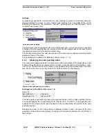
Page 13: ...software revision 1 1 on 4 3 3 Displaying the node guarding states The node guard mapping is used to represent the node guard states of the single slaves to the Profibus Always 8 slaves are represented in one byte so exactly one bit of information is reser ved for one This information can be shown in any desired spot in the Profibus data of the Gate way So they are shown in the input area of the P...

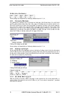
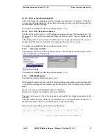
Page 14: ... the data of the EMCY message is shown in the bus data the new data in the Profibus is already visible with the toggle of the data Setting of the emergency messages These settings are available from Gateway software revision 1 1 on 4 3 5 Gateway control byte Some characteristics of the Gateway can be controlled by Profibus data For this the information of the Profibus has to be transmitted to the ...

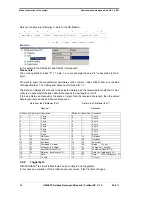
Page 15: ...ateway software revision 2 3 on 4 3 6 Gateway error byte The Gateway s current error state itselfcan be shown in the Profibus as well as the other values of the node guarding or the slave data Setting of the error byte This setting is available from Gateway software revision 1 1 on 4 3 7 SDO Obj Mapping Available from Gateway software revision 2 2 on SDO transfer through a window in the PB Here th...

Page 16: ...is cut off If the size Data Len Request is the same or larger than the receive data length then the actual data length comes back as Data Len Response Data from the PB Master PLC Data to the PB Master PLC Request Response PB Idx In Data Hex Description PB Idx In Data Hex Desription 0 1 byte 0 1 byte 1 2 byte 1 2 byte 2 3 byte 2 3 byte 3 4 byte 3 4 byte 4 5 byte 4 5 byte 5 6 byte 5 6 byte 6 7 byte ...

Page 17: ...tion is not transferred It is not a CANopen Slave conforming to the standards and an EDS file is not supplied 4 3 10 CAN Baud rate Available from the Gateway software revision 2 6 and WINGATE Built 376 on The CAN baud rate can be set via WINGATE The default setting DIP switch results in the baud rate being taken over by the DIP switch as usual 1 MBaud 500 kBd 250 kBd oder 125 kBd In case a baud ra...

Page 18: ...me Cycle times of data through the Gateway Among other things the actual cycle time of data from CANopen to Profibus or the other way round depends on the following parameters Amount of Mappings Length of the configured Profibus data Amount of COB IDs used at the Mappings Amount of changed Profibus data between two transmissions Amount of mapped bytes in a COB ID Baud rate in the Profibus or CAN O...

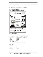
Page 19: ...GATE CANopen ProfibusDP 5 2 Configuration 5 2 1 Profibus Configuration data In accordance with GSD file DAGW2862 gsd Diagnostic data Max 8 bytes see Chapter Error handling Baud rate Automatic detection up to 12 MBaud Sync Supported Freeze Supported Ident No 0x2862 5 2 2 CANopen Baud rate In accordance with DIP Switch 5 2 3 RS232 Start bit 1 Data bits 8 Stop bit 1 Parity None Baud rate 9600 Baud ...

Page 20: ...t output signal from Profibus 4 5 M5 DGND data reference potential 6 P5 5 V supply voltage 7 8 A Inverting input output signal from Profibus 9 5 3 3 CANopen connector The connector labelled CANopen for connection to CANopen is located on the underside of the device Pin assignment 9 pin D SUB plug Pin No Name Function 1 2 CAN L Dominant low 3 CAN GND CAN Ground 4 5 6 7 CAN H Dominant high 8 9 5 3 4...

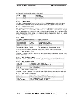
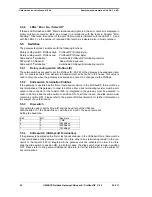
Page 21: ... LED Profibus Power green Profibus supply voltage LED Profibus State red green Interface status ProfibusDP LED CANopen Power green Supply voltage CANopen LED CANopen State red green Interface status CANopen LED Error No Select ID yellow Binary display of the connection error number In the configuration mode these displays are not valid and only meant for internal use 5 4 1 LED Profibus Error This ...

Page 22: ...nged via the Profibus 5 5 2 Slide switch Termination Profibus If the gateway is operated as the first or last physical device in the ProfibusDP there must be a bus termination at this gateway In order to do this either a bus terminating resistor must be acti vated in the connector or the resistor 220 integrated in the gateway must be activated In order to do this slide the slide switch to position...

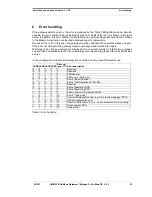
Page 23: ...played for one minute simply for information purposes and are then automatically reset If such warnings occur frequently please inform the after sales service In the configuration mode these displays are not valid and only meant for internal use LED8 LED4 LED2 LED1 Error no resp ID Error description 0 0 0 0 0 Reserved 0 0 0 1 1 Reserved 0 0 1 0 2 EEROM error 0 0 1 1 3 RAM error or ASIC error 0 1 0...

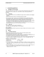
Page 24: ... piece of the device 7 1 2 Removal First disconnect the power supply and signal lines Then push the module up and swivel it out of the DIN rail Vertical installation The standard mounting channel may also be mounted vertically so that the module is mounted turned through 90 7 2 Wiring 7 2 1 Connection systems The following connection systems must resp may be used when wiring the module Standard sc...

Page 25: ... the device This guarantees higher interference immunity of the module since the cable shield current which may be up to a few Amperes owing to potential differences between two bus users is not discharged via the device If the device is subject to high mechanical or chemical stress it is advisable to use a tin plated DIN rail in order to ensure greater contact stability of the shield connection 7...

Page 26: ...arth via the shielding bus which is con nected conductively to the chassis or housing A low impedance connection to the PE wire is particularly important in order to prevent these interference currents themselves becoming an interference source Wherever possible use only lines with braided shield The coverage density of the shield should exceed 80 Avoid lines with foil shield since the foil can be...

Page 27: ... of the line into the cabinet connect the shield to a shielding bus Continue the shield as far as the module but do not connect it again at this point Downstream of the entry point into the switch cabinet the CANopen cable shield and the Pro fibusDP cable shield must be connected to the equipotential bonding strip Shielded data lines and unshielded power supply lines 60 V DC are routed to and conn...

Page 28: ...anning tool where he may also if necessary enter the address range in which the useful data is stored You can write up to 16 bytes or words in one octet of the DataUnit DU Inputs and outputs having the same format can be combined in one octet Otherwise you must use as many octets as the number of different bytes words you wish to use and which cannot be combined in one octet If the module detects ...

Page 29: ...stic information items 6 bytes and a user specific diagnostic information item Error number Telegram for diagnostic request Octet 1 0 Diag station does not exist sets Master Diag station not_ready Slave is not ready for data exchange Diag cfg_Fault Configuration data does not correspond Diag ext_diag Slave has external diagnostic data Diag not supported Requested function is not supported in the S...

Page 30: ...ived Sync_mode Sync command received reserved Diag deactivated sets Master Octet 3 0 reserved Diag ext_overflow Octet 4 0 Diag master_add Master address after programming FF without programming Octet 5 0 Ident number high byte Octet 6 0 Ident number low byte Representation of the data in ProfibusDP Deutschmann Automation GmbH Co KG 30 UNIGATE Fieldbus Gateway CANopen ProfibusDP V 2 3 26 8 11 ...

Page 31: ...presentation of the data in ProfibusDP 8 4 Data exchange After the Master in the diagnostic detects that the Slave is ready for data exchange it sends data exchange telegrams Either the Master stores the data in the input output direction in the address area specified during project planning or the control program must fetch or retrieve the data using specific function blocks ...

Page 32: ...0 Atmospheric pressure during operation during transport 795 hPa 1080 hPa 660 hPa 1080 hPa 11 Installation altitude 2000 m 4000 m Unrestricted Restricted Ambient temperature 40 ºC 12 Relative humidity Max 80 No condensation no corrosive atmosphere 13 Particles dirt Sand and dust may not penetrate the device 14 External power supply 10 8 30 V DC Standard power supply unit to DIN 19240 15 Current co...

Page 33: ...min 10 frequency sweeps each in x y z IEC 68 2 6Fc sinusoidal 2 Shock test Shock waveform semi sinusoidal Acceleration 15g 150 m s2 Shock duration 11 ms 3 shocks in direction in x y z IEC 68 2 27 Ea 3 ESD 8 kV discharge in air 4 kV contact discharge EN 50082 2 4 Electromagnetic fields 10 V m EN 50082 2 5 BURST 2 kV 5 kHz supply voltage 1 kV 5 kHz data lines EN 50082 2 6 Emitted interference Limit ...

Page 34: ... Maximum Baud rate dependent 1200 m 93 75 kBd 1200 m 187 5 kBd 1000 m 500 kBd 400 m 1 5 MBd 200 m 1 5 MBd 100 m 15 m No 1300 m 50 kBd 1300 m 100 kBd 640 m 200 kBd 310 m 500 kBd 112 m 1 MBd 40 m 6 Bus topology Line Point to point Line 7 Data rate Maximum Standard values 12 Mbit s 9 6 kBit s 19 2 kBit s 93 75 kBit s 187 5 kBit s 500 kBit s 1 5 Mbit s 3 MBit s 6 MBit s 12 Mbit s 38 4 kBit s 2 4 k B 4...

Page 35: ... use The device is designed for snapping onto a 35 mm DIN rail 10 4 Commissioning It is essential that you perform the following steps during commissioning in order to ensure that the module operates correctly 10 5 Setting the Profibus address Set the Profibus address at the fieldbus end of the module on the two rotary switches designated Profibus ID Attention The Profibus address set must corresp...

Page 36: ...le has been snapped 10 11 Project planning Use any project planning tool for project planning If the required GSD file was not supplied with your project planning tool please copy this file from the enclosed diskette or download this file from the Internet www deutschmann de 10 12 Literature We recommend that you read book Schnelleinstieg in ProfibusDP author M Popp to help you quickly get to grip...

Page 37: ...Germany Tel 49 6434 9433 0 Fax 49 6434 9433 44 Hotline 49 6434 9433 33 E mail service deutschmann de 11 1 Returning a device If you return a device we require as comprehensive a fault error description as possible We require the following information in particular What error number was displayed What is the supply voltage 0 5 V with gateway connected What were you last doing or what last happened ...

Page 38: ... Fieldbus Gateway CANopen ProfibusDP V 2 3 26 8 11 12 Annex 12 1 Hexadecimal table Hex Decimal Binary 0 0 0000 1 1 0001 2 2 0010 3 3 0011 4 4 0100 5 5 0101 6 6 0110 7 7 0111 8 8 1000 9 9 1001 A 10 1010 B 11 1011 C 12 1100 D 13 1101 E 14 1110 F 15 1111 ...

Page 39: ...EMV Guideline 92 31 EWG This is to declare that we company Deutschmann Automation GmbH Max Planck Straße 21 D 65520 Bad Camberg developed produced and offered the below mentioned product for sale in correspondence with the above mentioned EG guideline Product Gateway Type designation UNIGATE CANopen Master ProfibusDP Slave Applied standards EN 50082 2 EN 550011 Bad Camberg Gunther Lawaczeck Michae...

Page 40: ...EG Certificate of Conformance Deutschmann Automation GmbH Co KG 40 UNIGATE Fieldbus Gateway CANopen ProfibusDP V 2 3 26 8 11 ...

Page 41: ...26 8 11 UNIGATE Fieldbus Gateway CANopen ProfibusDP V 2 3 41 Deutschmann Automation GmbH Co KG EG Certificate of Conformance ...

Page 42: ...EG Certificate of Conformance Deutschmann Automation GmbH Co KG 42 UNIGATE Fieldbus Gateway CANopen ProfibusDP V 2 3 26 8 11 ...

Reviews: