background image


7 

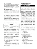
2.6.1  Masonry chimney 

This furnace can be vented into an existing masonry chimney. 
However,  the  unit  must  not  be  vented  into  a  chimney  into 
which a solid fuel burning furnace is already being vented. 


Before  venting this furnace into a chimney, its condition must 
be checked and repairs made, if necessary. Also, the chimney 
lining  and  dimensions  must  conform  to  local  and  national 
codes. 


2.6.2  Factory Built Chimneys


Oil  fired  furnaces  are  approved  for  use  with  “L”  type  vents. 
The  unit  may  also  be  used  with  an  approved  chimney  of 
proper dimensions and temperature ratings as specified in the 
installation code. Refer to chimney manufacturer’s instructions 
for proper installation. 

2.6.3  Draft Regulator 

It  is  recommended that a draft regulator be installed in cases 
where  the  draft  is  either  high  or  variable  due  to  external 
conditions. Follow the instructions provided with the regulator.


2.6.4  Side-wall Venting 


The heating unit is approved for side-wall venting. This system 
includes model VTK-3 / KLAVT0201DET side-wall venter and 
a 5” insulated vent pipe, model IFV5 / KLAFVxx01DET. Refer 
to  the  installation  instructions  provided  with  the  venting 
system. 

2.7  BLOCKED


VENT


SHUT-OFF


DEVICE


(BVSO)


FOR


CHIMNEY


VENTING 

CAUTION 

It  is  imperative  that  this  device  be  installed  by  a  qualified 
service technician. 


A  positive  pressure  venting  system  (Sealed  Combustion 
System  or  Direct  Vent)  MUST  NOT  use  the  BVSO.  Follow  the 
instructions supplied with the venting system. 


This device is designed to detect the insufficient evacuation of 
combustion  gases  in  the  event  of  a  vent  blockage.  In  such  a 
case  the  thermal  switch  will  shut  down  the  oil  burner.  The 
device will then need to be re-armed MANUALLY. 


Refer to the detailed instructions and wiring diagrams supplied 
with the BVSO for the installation and wiring procedures. The 
length  of  wires  supplied  with  the  unit  is  such  that  the  safety 
device  must  be  installed  between  the  flue  outlet  of  the 
appliance  and  the  draft  regulator,  as  indicated  in  the 
instructions. 


It is also essential that the BVSO be maintained annually. For 
more  details  refer  to  the  instructions  supplied  with  the  device 
itself, as well as Section 3. of this Manual. 
 

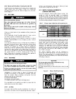
2.7.1  BVSO Performance Test 


The purpose of the following test is to check that the electrical 
outlet on the furnace, designated to the BVSO, is functional. 


1.  Start up the burner; 
2.  Remove the three-pole plug from the BVSO outlet on the 

furnace; 

3.  The  burner  must  shut-off  immediately,  while  the  blower 

continues to run to the end of the cool-down cycle. 


If  the  test  is  not  in  line  with  the  above,  call  a  QUALIFIED 
SERVICE TECHNICIAN. 


2.8  COMBUSTION


AIR


SUPPLY 

AND


VENTILATION 


WARNING


Poisonous carbon monoxide gas hazard. 


Comply  with  NFPA  31  (U.S.)  and  CSA  B139  (Canada) 
standards  for  the  installation  of  Oil  Burning 
Equipment and applicable provisions of local building 
codes to provide combustion and ventilation air. 


Failure 

to 

provide 

adequate 

combustion 

and 

ventilation air can result in death, bodily injury and/or 
property damage. 


Oil  furnaces  must  have  an  adequate  supply  of 
combustion  air.  It  is  common  practice  to  assume  that 
older  homes  have  sufficient  infiltration  to  accommodate 
the combustion air requirement for the furnace. However, 
home  improvements  such  as  new  windows,  doors,  and 
weather  stripping  have  drastically  reduced  the  volume  of 
air infiltration into the home. 


Refer  to  oil  furnace  installation  codes  relative  to 
combustion  and  ventilation  air  requirements.  Consult 
Section  2.2  in  this  manual,  specifically  for  units  installed 
in an enclosed space.  


Home air exhausters are common. Bathroom and kitchen 
fans,  power  vented  clothes  dryers  and  water  heaters  all 
tend to create a negative pressure condition in the home. 
Should  this  occur  the  chimney  becomes  less  and  less 
effective  and  can  easily  downdraft.  In  certain  cases, 
mechanically supplied air, by way of a blower, interlocked 
with  the  unit,  is  necessary.  It  is  the  installer’s 
responsibility to check that. 

2.8.1 

Contaminated Combustion Air  

Installations  in  certain  areas  or  types  of  structures  will 
increase the exposure to chemicals or halogens that may 
harm  the  furnace.  These  conditions  will  require  that  only 
outside air be used for combustion. 


The following areas or types of structures may contain or 
be  exposed  to  certain  substances,  potentially  requiring 
outside air for combustion: 


a.  Commercial buildings; 
b.  Buildings with indoor pools; 
c. 

Furnaces installed near chemical storage areas. 


Exposure to the following substances: 
a.  Permanent wave chemicals for hair; 
b.  Chlorinated waxes and cleaners; 
c. 

Chlorine based swimming pool chemicals; 

d.  Water softening chemicals; 
e.  De-icing salts or chemicals; 
f. 

Carbon Tetrachloride; 

g.  Halogen type refrigerants; 
h.  Cleaning solvents (such as perchloroethylene); 
i. 

Printing inks, paint removers, varnishes, etc. ; 

j. 

Hydrochloric acid; 

k. 

Solvent based glue; 

l. 

Antistatic fabric softeners for clothes dryers; 

m.  Acid based masonry cleaning materials. 

Summary of Contents for AMP154SD

Page 1: ...erbrooke Québec Canada J1L 1V8 www dettson ca Attention Do not tamper with the unit or its controls Call a qualified service technician INSTALLER SERVICE TECHNICIAN USE THE INFORMATION IN THIS MANUAL FOR THE INSTALLATION SERVICING OF THE FURNACE AND KEEP THE DOCUMENT NEAR THE UNIT FOR FUTURE REFERENCE HOMEOWNER PLEASE KEEP THIS MANUAL NEAR THE FURNACE FOR FUTURE REFERENCE US C DNS 1225A ...

Page 2: ...s of ventilation air openings in a closet door 4 Figure 2 Upflow Installation 4 Figure 3 Downflow Installation 5 Figure 4 Horizontal Installation 5 Figure 5 Thermostat wiring heating and air conditioning with 4 speed motor 5 Figure 6 Thermostat wiring heating and air conditioning with ECM variable speed motor 6 Figure 7 Thermostat wiring heating and air conditioning heat pump with ECM variable spe...

Page 3: ...nformation such as the model and serial numbers of the furnace WARNING Installations and repairs performed by unqualified persons can result in hazards to them and to others Installations must conform to local codes or in the absence of same to codes of the country having jurisdiction The information contained in this manual is intended for use by a qualified technician familiar with safety proced...

Page 4: ... designed for outdoor installation It must be installed in such a manner as to protect its electrical components from water Outdoor installation will lead to a hazardous electrical condition and to premature failure of the equipment The minimum clearances from combustible material for each of the positions are specified in Table 4 If the furnace is installed in a basement or on a dirt floor in a c...

Page 5: ...ground to minimize the risk of bodily harm if ever an electrical problem develops A green ground screw is supplied with the control box for that purpose The appliance must be installed in accordance with the current ANSI NFPA 70 National Electrical Code CSA C22 1 Canadian Electrical Code Part 1 and or local codes The control system depends on the correct polarity of the power supply Connect HOT wi...

Page 6: ...own in table 1 and based on a pump pressure of 100 psi Always select nozzle sizes by working back from the desired flow rate at operating pressure and not the nozzle marking 2 5 2 Air and Turbulator Settings Before starting the burner for the first time adjust the air and turbulator settings to those listed in this manual Once the burner becomes operational final adjustments will be required Refer...

Page 7: ...ove the three pole plug from the BVSO outlet on the furnace 3 The burner must shut off immediately while the blower continues to run to the end of the cool down cycle If the test is not in line with the above call a QUALIFIED SERVICE TECHNICIAN 2 8 COMBUSTION AIR SUPPLY AND VENTILATION WARNING Poisonous carbon monoxide gas hazard Comply with NFPA 31 U S and CSA B139 Canada standards for the instal...

Page 8: ...at only outside air be used for combustion a Commercial buildings b Buildings with indoor pools c Furnaces installed near chemical storage areas The installation must carefully be verified to ensure that the combustion air comes from outside 2 10 1 Air filter A properly sized air filter must be installed on the return air side of the unit Refer to the Technical Specifications table 6 for the corre...

Page 9: ...fier on the HUM terminal It supplies 120 VAC electric power when the burner is in operation A 24 VAC signal can also be supplied from the W and C terminals on the blower electronic board to activate a switching relay Also refer to the instructions supplied with the accessory 2 13 2 Electronic Air Cleaner EAC The EAC terminal on the electronic board supplies 120 VAC when the blower is operating in ...

Page 10: ...he oil piping and pump Slowly close and tighten the bleed screw Once closed the flame will light up 3 3 2 Pressure adjustment The oil pressure must be adjusted according to the Technical Specifications of this manual An adjustment screw and a connection for a pressure gauge are located on the oil pump for that purpose Also refer to the burner instruction manual 3 3 3 Combustion Check IMPORTANT The...

Page 11: ...iant heat from the heat exchanger 0 3 m 12 from the plenum of the main take off is usually sufficient 4 The temperature rise is calculated by subtracting the return air temperature from the supply air temperature 5 If the temperature rise is lower or exceeds the temperature specified in Table 6 change to the next lower or higher blower speed tap until the temperature rise falls to the target If th...

Page 12: ...t exchanger and combustion chamber should be inspected to determine if replacement is required 8 After the cleaning replace the heat exchanger baffles flue collar plate and oil burner 9 Readjust the burner for proper operation 4 2 CLEANING THE BLOCKED VENT SHUT OFF DEVICE BVSO For continuous safe operation the Blocked Vent Shut off device BVSO must be inspected and maintained annually by a qualifi...

Page 13: ...rvice telephone Day Night Dealer name and address START UP RESULTS Nozzle Pressure lb po2 Burner adjustments Primary air Fine air Drawer Assembly CO2 Smoke scale Bacharach Gross stack temperature F Ambient temperature F Chimney draft W C Overfire draft W C Test performed by ...

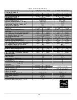
Page 14: ...A 0 90 70A Minimum and Maximum pump pressure PSIG 145 150 145 150 Combustion air adjustment turbulator damper 1 0 3 75 3 0 4 25 1 0 3 75 3 0 4 25 AFUE From CSA B212 standard and Canadian regulation 86 4 85 7 86 4 85 7 AFUE From ASHRAE 103 standard and US regulation 86 1 85 0 86 1 85 0 Volts Hertz Phase Rated current Amps Minimum ampacity for wire sizing Amps Max fuse size Amps Control transformer ...

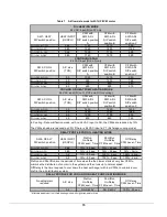
Page 15: ...n Delay CFM Level Time Off Delay CFM Level Time A 1 OFF 2 OFF 0 68 13 45 sec 19 60 sec 38 3 min B 1 ON 2 OFF 0 80 13 45 sec 19 30 sec 38 3 min C 1 OFF 2 ON All 13 45 sec 100 0 sec 100 2 min D 1 ON 2 ON All 13 90 sec 100 0 sec 100 2 min No adjustment required A C size PreRun On Delay CFM Level Time ShortRun On Delay CFM Level Time Off Delay CFM Level Time All NO DELAY NO DELAY 100 90 sec OIL HEATIN...

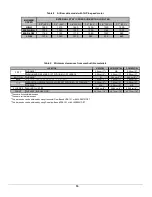
Page 16: ...F FURNACE 1 5 08 cm 2 2 54 cm 1 5 08 cm 2 BOTTOM FURNACE 2 Ø 2 54 cm 1 3 5 08 cm 2 4 BACK FURNACE OPPOSITE SIDE OF THE BURNER 1 7 62 cm 3 7 62 cm 3 7 62 cm 3 PLENUM OR HORIZONTAL WARM AIR DUCT WITHIN 6 ft OF FURNACE 2 5 08 cm 2 7 62 cm 3 5 08 cm 2 FURNACE 2 N A 5 08 cm 2 N A FLUE PIPE AROUND FLUE PIPE 22 86 cm 9 22 86 cm 9 22 86 cm 9 FRONT FURNACE BURNER SIDE 1 45 72 cm 18 45 72 cm 18 45 72 cm 18 ...

Page 17: ...17 Figure 9 Furnace Dimensions ...

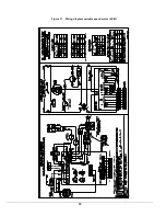
Page 18: ...18 Figure 10 Wiring diagram 4 speed motor PSC ...

Page 19: ...19 Figure 11 Wiring diagram variable speed motor ECM ...

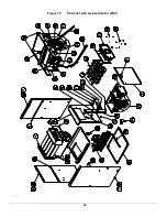
Page 20: ...20 Figure 12 Parts list with 4 speed motor PSC B500111A ...

Page 21: ...640 WIRE CHANNEL INT 30 B03829 BLOWER DIVIDER 31 B03838 BLOWER SLIDE One blower slide included 32 B03835 02 LATERAL BAFFLE 33 B03867 01 FILTER RACK KIT 34 B03828 FLOOR 35 B03855 02 SIDE PANEL ASSEMBLY LEFT Panel insulation and baffle included 36 B03857 REAR PANEL ASSEMBLY Panel insulation and baffles included 37 B03864 REAR PANEL INSULATION 38 B03836 REAR BAFFLE 39 B01682 SUPPORT ELECTRONICS BOX 4...

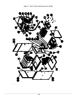
Page 22: ...22 Figure 13 Parts list with variable speed motor ECM B50112A ...

Page 23: ...CHANNEL INT 29 B03829 BLOWER DIVIDER 30 B03838 BLOWER SLIDE One blower slide included 31 B03835 02 LATERAL BAFFLE 32 B03867 01 FILTER RACK KIT 33 B03828 FLOOR 34 B03855 02 SIDE PANEL ASSEMBLY LEFT Panel insulation and baffle included 35 B03857 REAR PANEL ASSEMBLY Panel insulation and baffles included 36 B03864 REAR PANEL INSULATION 37 B03836 REAR BAFFLE 38 B01682 SUPPORT ELECTRONICS BOX 39 L01F009...

Reviews: