


Assembly and Wiring Procedure
Connect the external wiring to the appropriate terminals
on the DCU terminal wiring board. See Figure 9.
IMPORTANT
Insulate the shields to prevent shorting to the
device housing or to any other conductor.
Attach the sensor to the DCU enclosure. Do not over-
tighten. If a sensor separation kit is being used, attach
the sensor to the separation kit junction box and wire
the device as described below.
CAUTION
The sensor threads can be coated with an appro-
priate grease to ease both the initial installation
and future replacement of the sensor. Detector
Electronics offers a silicone free grease that is
especially suited for use with catalytic type com-
bustible gas sensors (part number 102868-001).
The use of other lubricants is not recommended,
since some materials can cause irreversible dam-
age to the sensing element. SILICONE based
lubricants or compounds must NEVER be used.
Screw the transmitter board to the standoffs as shown in
Figure 8. Connect the sensor plug to the transmitter
board.
Attach the communication module to the standoffs
mounted on the transmitter board. Connect the ribbon
cable from the terminal wiring board to the communica-
tion module.
Set the address for the device (see “Addressability” on
page 3).
Sensor Separation with DCUEX
If the installation requires mounting the sensor in a dif-
ferent location than the DCUEX, observe the following
guidelines.
When separating a combustible gas sensor from the
DCUEX, two options exist:
1. Preferred Method
Mount the transmitter PC board inside the sensor
separation junction box. This assembly can be
separated from the DCUEX by up to 1000 feet using
three conductor 18 AWG shielded cable.
(Regardless of separation distance, operating volt-
age at the transmitter MUST be at least 18 vdc to
ensure proper operation.) See Figure 10.
Assemble the DCUEX without the transmitter board
similar to the DCU as shown in Figure 4. Plug the
sensor into P2 on the transmitter board. Use a
three conductor 18 AWG shielded cable to connect
P1 on the transmitter board to terminals 2, 3 and 4
on the DCU terminal board (see Figure 10).
Connect the shield to the ground terminal in the
DCUEX junction box.
2.
Alternate Method.
If the transmitter board must be mounted separate
from the sensor (high temperature applications,
etc.), separate the sensor only, leaving the transmit-
ter PC board inside the DCUEX enclosure. When
using this installation option, see Table 2 for maxi-
mum wiring distances.
Mount the sensor directly to the separation kit junc-
tion box. Use three conductor shielded cable for
the connection between the terminal block in the
separation kit junction box and P1 on the transmitter
board. A plug with screw terminals is provided for
connecting the cable to P1 on the transmitter board.
Observe the wiring color code. Connect the shield
to the ground terminal in the DCUEX junction box.
7
90-1118
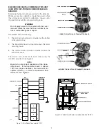
1
2
3
4
5
6
7
8
9
10
SIG
–
+
DCU TERMINAL BOARD
DCU TRANSMITTER BOARD1
(MIDDLE BOARD)
14
13
12
11
–
–
+
+
24 VDC
POINTWATCH CALIBRATE
4 TO 20 MA IN
–
+
A
B
A
B
SENSOR POWER
COM 2
COM SHIELD
COM 1
B1877
NOTES: 1 Catalytic Combustible Gas Sensor
Plugs into Connector Pins on the
Middle Board inside the Junction Box.
2 Connections Wired at the Factory.
2
2
2
Figure 9—DCU Transmitter Board Connected
to Terminal Wiring Board


