


IMPORTANT
Insulate the shields to prevent shorting to the
device housing or to any other conductor.
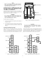
Attach the communication module to the standoffs as
shown in Figure 4. Connect the ribbon cable from the
terminal wiring board to the communication module.
Set the address for the device (see “Addressability” on
page 3).
Check the wiring to ensure proper connections, then
pour the conduit seals and allow them to dry (if conduit
is being used).
NOTE
Before placing the cover back on the enclosure fol-
lowing completion of assembly and wiring, inspect
the enclosure O-ring to be sure that it is in good
condition and properly installed. Lubricate the O-
ring and the threads of the cover with a thin coat of
an appropriate grease to ease installation. If the
installation uses catalytic type combustible gas
sensors, it is imperative that lubricants containing
silicone NOT be used, since they will cause irre-
versible damage to the sensor. Place the cover on
the enclosure. Tighten only until snug. Do not
over tighten.
SENSOR SEPARATION FOR DCU WITH H2S AND
O2 SENSORS
Since the transmitter for the electrochemical sensor is
already mounted within the sensor housing, simply
mount the entire sensor assembly to the sensor separa-
tion kit junction box and wire it to terminals 2 and 4
inside the DCU, the same as a regular (without sensor
separation) installation. Connect the shield to the
ground terminal in the DCU junction box.
Refer to Table 1 for separation distance limitations for
H
2
S/toxic/O
2
sensors.
EQ2200DCU DIGITAL COMMUNICATION UNIT
USED WITH POINTWATCH
Determine the best mounting locations for the detectors.
Whenever practical, detectors should be placed where
they are easily accessible for calibration.
WARNING
Do not apply power to the system with the cover
removed unless the area has been verified to be
free of combustible gases and vapors.
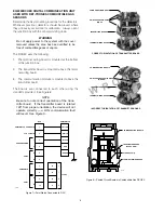
The DCU utilizes the following:
1.
A terminal wiring board mounted at the bottom of
the junction box.
2.
A communication module mounted above the termi-
nal wiring board using the standoffs provided. See
Figure 4.
Assembly and Wiring Procedure
Attach the PointWatch to the DCU enclosure. Do not
over-tighten. If a sensor separation kit is used, attach
the sensor to the separation kit junction box and wire the
device as described in the “Sensor Separation” section.
Refer to the PointWatch manual (form 95-8440) for com-
plete installation and application information.
Refer to Figure 7 when wiring a PointWatch IR gas
detector and a DCU. The wiring code for PointWatch is:
Red =
+ (24 vdc)
Black =
– (common)
White =
4 to 20 ma signal
Yellow =
Calibration input
Green =
Chassis ground
IMPORTANT
Insulate the shields to prevent shorting to the
device housing or to any other conductor.
Set the address for the device (see “Addressability” on
page 3).
Sensor Separation for DCU with PointWatch
Shielded four wire cable is recommended for connect-
ing the detector junction box to the DCU. Cable with a
foil shield is recommended. The shield of the cable
should be open at the detector junction box and con-
nected to earth ground on the DCU junction box.
NOTE
To ensure proper operation, a minimum of 18 vdc
(including ripple) must be maintained at the PointWatch.
5
90-1118
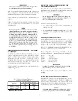
Table 1—Maximum Separation Distances —
Electrochemical Sensor to DCU
Wire Size
Maximum Wiring Distance
Feet
Meters
18 AWG (1.0 mm2)*
5700
1750
16 AWG (1.5 mm2)*
9000
2800
* Approximate Metric Equivalent.


