


EQ2200DCUEX DIGITAL COMMUNICATION UNIT
USED WITH DET-TRONICS COMBUSTIBLE GAS
SENSORS
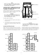
Determine the best mounting locations for the detectors.
Whenever practical, detectors should be placed where
they are easily accessible for calibration. Always orient
the junction box with the sensor pointing down.
WARNING
Do not apply power to the system with the cover
removed unless the area has been verified to be
free of combustible gases or vapors.
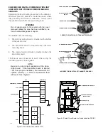
The DCUEX uses the following:
1.
The terminal wiring board is mounted at the bottom
of the junction box.
2.
The transmitter board is mounted above the termi-
nal wiring board.
3.
The communication module is mounted above the
transmitter board.
The boards are connected to each other using the
standoffs provided. See Figure 8.
NOTE
Be sure to note correct orientation of the trans-
mitter board. If the transmitter board is rotated
180° from proper orientation, the device will not
operate correctly — a LON communication fault
will result. See Figure 8.
6
W
R O
N G
COMMUNICATION MODULE
SWITCHES ON SAME SIDE
(RIGHT)
TRANSMITTER BOARD
TERMINAL WIRING BOARD
CORRECT ORIENTATION OF TRANSMITTER BOARD
COMMUNICATION MODULE
SWITCHES ON OPPOSITE SIDES
(WRONG)
TRANSMITTER BOARD
TERMINAL WIRING BOARD
INCORRECT ORIENTATION OF TRANSMITTER BOARD
C1570
COMMUNICATION MODULE
TRANSMITTER BOARD
(DCUEX ONLY)
STANDOFFS (4)
TERMINAL WIRING BOARD
Figure 8—Printed Circuit Boards in Combustible Gas DCUEX
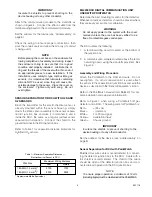
1
2
3
4
5
6
7
8
9
10
YELLOW
WHITE
BLACK
RED
GREEN
DCU
POINTWATCH
14
13
12
11
–
–
+
+
24 VDC
POINTWATCH CALIBRATE
4 TO 20 MA IN
–
+
A
B
A
B
SENSOR POWER
COM 2
COM SHIELD
COM 1
A1876
Figure 7—PointWatch Connected to DCU


