


NOTE
Refer to the Eagle Quantum system manual,
form number 95-8470, for complete instructions
regarding wiring and installation.
EQ2200DCU DIGITAL COMMUNICATION UNIT USED
WITH DET-TRONICS H
2
S/O
2
SENSORS OR OTHER
TWO-WIRE 4 TO 20 MA DEVICES
Determine the best mounting locations for the detectors.
Whenever practical, detectors should be placed where
they are easily accessible for calibration.
WARNING
Do not apply power to the system with the cover
removed unless the area has been verified to be
free of combustible gases or vapors.
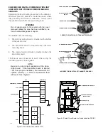
The DCU utilizes the following:
1.
A terminal wiring board mounted at the bottom of
the junction box.
2.
A communication module mounted above the termi-
nal wiring board using the standoffs provided. See
Figure 4.
Assembly and Wiring Procedure
Attach the sensor to the DCU enclosure. Do not over-
tighten. If a sensor separation kit is used, attach the
sensor to the separation kit junction box and wire the
device as described in the “Sensor Separation” section.
CAUTION
The sensor threads can be coated with an appro-
priate grease to ease installation. Also lubricate
the cover threads.
Connect the external wiring to the appropriate terminals
on the DCU terminal wiring board. Refer to Figure 5 for
terminal identification. See Figure 6 for an example of a
Det-Tronics electrochemical sensor wired to a DCU.
4
A1571
COMMUNICATION MODULE
STANDOFFS (4)
TERMINAL WIRING BOARD
Figure 4—Printed Circuit Boards in Universal DCU
1
2
3
4
5
6
7
8
9
10
14
13
12
11
–
–
+
+
24 VDC
POINTWATCH CALIBRATE
4 TO 20 MA IN
–
+
A
B
A
B
SENSOR POWER
COM 2
COM SHIELD
COM 1
A1726
Figure 5—Terminal Identification for DCU
1
2
3
4
5
6
7
8
9
10
BLACK
RED
GREEN
DCU
H2S/TOXIC/O2
14
13
12
11
–
–
+
+
24 VDC
POINTWATCH CALIBRATE
4 TO 20 MA IN
–
+
A
B
A
B
SENSOR POWER
COM 2
COM SHIELD
COM 1
A1875
Figure 6—Electrochemical Sensor Connected to DCU


