background image

TB-3043

 Page 3 of 6

© 2019 DESCO INDUSTRIES INC

Employee Owned

DESCO WEST 

- 3651 Walnut Avenue, Chino, CA 91710 • (909) 627-8178

DESCO EAST 

- One Colgate Way, Canton, MA 02021-1407 • (781) 821-8370 • Website: 

Desco.com

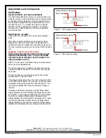
Voltage Selection Header
Power Jack

Jumpers

Figure 3.  110V jumper setting

Voltage Selection Header
Power Jack

Jumpers

Figure 4.  220V jumper setting

Adjustments and Compliance 

Verification

BALANCE OFFSET VOLTAGE ADJUSTMENT

The High Output Benchtop Ionizer is an auto-balancing unit.  

However, tuning or manual adjustment can be accomplished 

by inserting a small screwdriver or trimmer adjustment tool 

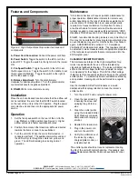
into the balance adjustment hole located at the rear of the 

unit (see Figure 2).  To increase the output in a positive 

direction, turn the potentiometer clockwise.  To increase 

the output in a negative direction, turn the potentiometer 

counter-clockwise.

MAINTENANCE / ALARMS

In the event of circuit failure, the unit will enter shutdown 

mode.
When the unit enters shutdown mode, ionization will be 

stopped, the LED on the front of the unit will illuminate a 

constant red, and the audible alarm will continuously sound.  

The user must then reset the unit by turning it OFF and back 

ON.

WARNING - RISK OF ELECTRIC SHOCK

THESE SERVICING INSTRUCTIONS ARE FOR USE BY 

QUALIFIED PERSONNEL ONLY.  DO NOT PERFORM 

ANY SERVICING OF INTERNAL PARTS UNLESS YOU 

ARE QUALIFIED TO DO SO.

NOTE:  The AC power cord MUST always be disconnected 

before the unit is disassembled.  
The input voltage may be verified or reset by removing the 

3 screws located on the back of the unit then removing the 

back case. 
The input voltage can be selected using the two internal 

jumpers shown in Figures 3 and 4.
If the supply voltage drops from 110 Volts to below 85 Volts 

or from 200 Volts to below 170 Volts, the unit will shut down, 

the audible alarm will beep and the LED will blink red.  The 

unit will automatically reset when the minimum voltage is 

restored.
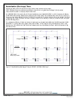
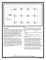
Compliance Verification should be per ESD TR53. Offset 

voltage (balance) and both polarity’s discharge time should 

be checked on every ionizer periodically using an Ionization 

Test Kit or a Charged Plate Analyzer.  Measure offset 

voltage (balance) and both polarity’s discharge times.  Clean 

the emitter points (with electrical power off), adjust offset 

voltage (balance) to zero and then re-test for offset voltage 

(balance) and discharge times recording the measurements. 

Summary of Contents for 60506

Page 1: ...rrounding air When an electrostatic charge is present on objects in the work environment it will be neutralized by attracting opposite polarity charges from the ionized air Note that ionization systems should not be used as a primary means of charge control on conductors or people Reference EN 61340 5 2 1 clause 5 2 9 September 2019 The primary method of static charge control is direct connection ...

Page 2: ...nit OFF and unplug the power cord A B C E D Figure 2 High Output Benchtop Ionizer features and components A Power Cord Connection Connect the power cord here B Power Switch Toggle the switch to the left to turn the ionizer OFF Toggle the switch to the right to turn the ionizer ON C Fan Speed Switch Toggle the switch to the left to set the fan speed to Low Toggle the switch to the middle to set the...

Page 3: ...will continuously sound The user must then reset the unit by turning it OFF and back ON WARNING RISK OF ELECTRIC SHOCK THESE SERVICING INSTRUCTIONS ARE FOR USE BY QUALIFIED PERSONNEL ONLY DO NOT PERFORM ANY SERVICING OF INTERNAL PARTS UNLESS YOU ARE QUALIFIED TO DO SO NOTE The AC power cord MUST always be disconnected before the unit is disassembled The input voltage may be verified or reset by re...

Page 4: ...ments recorded in a factory ambient environment Per ANSI ESD S20 20 the test method for Product Qualification test is ANSI ESD STM3 1 and for Compliance Verification is ESD TR53 which advises Measurements should be made at the location where ESD sensitive items are to be ionized A larger area may require additional ionizers Per S20 20 the required limit for ionizer discharge time is user defined U...

Page 5: ... the data can justify lengthening the calibration period If ionizers require adjustment the calibration period should be shortened Although ESD TR53 does not advise a test frequency JESDD625 A Revision of EIA 625 recommends ionizers be tested semiannually noting to use S3 1 except the number of measurement points and locations may be selected based on the application NOTE A charged plate analyzer ...

Page 6: ... W Dimensions including stand 9 5 H x 6 0 W x 3 1 D 241 mm x 152 mm x 79 mm Weight 4 5 lbs 2 0 kg Balance Offset Voltage at 12 3 V typical 25 V maximum Neutralization Discharge Time at 12 2 seconds Airflow Three speed fan 50 100 CFM Emitter Points 050 diameter tungsten Ion Emission Steady state DC with sense feedback Fuse 250 mA slow blow High Voltage Power Supply 5 5 kVDC nominal Ozone 0 05 ppm E...

Page 7: ...Mouser Electronics Authorized Distributor Click to View Pricing Inventory Delivery Lifecycle Information Desco 60505 60507 ...

Reviews: