TB-3043
Page 2 of 6
© 2019 DESCO INDUSTRIES INC
Employee Owned
DESCO WEST
- 3651 Walnut Avenue, Chino, CA 91710 • (909) 627-8178
DESCO EAST
- One Colgate Way, Canton, MA 02021-1407 • (781) 821-8370 • Website:
Features and Components
Maintenance
“All ionization devices will require periodic maintenance for
proper operation. Maintenance intervals for ionizers vary
widely depending on the type of ionization equipment and
use environment. Critical clean room uses will generally
require more frequent attention. It is important to set-up
a routine schedule for ionizer service. Routine service is
typically required to meet quality audit requirements.” (ESD
Handbook TR20.20 section 5.3.6.7 Maintenance / Cleaning)
EIA-625, recommends checking ionizers every 6 months, but
this may not be suitable for many programs particularly since
an out-of-balance may exist for months before it is checked
again. ANSI/ESD S20.20 section 6.1.3.1 Compliance
Verification Plan Requirement states: “Test equipment shall
be selected to make measurements of appropriate properties
of the technical requirements that are incorporated into the
ESD program plan.”
CLEANING THE EMITTER POINTS
The maintenance interval of the High Output Benchtop
Ionizer is extended with the use of its auto-balancing
closed-loop feedback technology. The ionizer will detect any
shifts in the offset voltage (balance) and adjust its output
to compensate for the change. This shift in offset voltage
(balance) is often caused by particle build-up on the ionizer’s
emitter points. To maintain optimum neutralization efficiency
and operation, cleaning should be performed on a regular
basis.
Use the included Emitter Point Cleaners or a swab
dampened with Isopropyl alcohol to clean the ionizer’s
emitter points.
1. Turn the unit OFF and unplug the power cord.
A
B
C
E
D
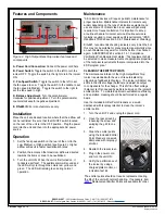
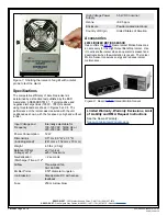
Figure 2. High Output Benchtop Ionizer features and
components
A. Power Cord Connection:
Connect the power cord here.
B. Power Switch:
Toggle the switch to the left to turn the
ionizer OFF. Toggle the switch to the right to turn the ionizer
ON.
C. Fan Speed Switch:
Toggle the switch to the left to set
the fan speed to Low. Toggle the switch to the middle to set
the fan speed to Medium. Toggle the switch to the right to
set the fan speed to High.
D. Balance Adjustment:
Turn the potentiometer
clockwise for positive adjustment. Turn the potentiometer
counter-clockwise for negative adjustment.
E. RS-485 IN:
For manufacturer use only.
Installation
Place the unit at a desired location where that the airflow will
not be restricted. Be sure that the ON/OFF switch located
on the rear of the unit is in the OFF position. Plug the power
cord into the unit and then into the appropriate AC power
source.
Operation
1. Set the fan speed switch on the rear of the unit to the
Low, Medium, or High position (see Figure 2). Higher
airflow will result in faster neutralization rates.
2. Position the ionizer so that maximum airflow is directed
towards the items or area to be neutralized.
3. Turn the unit ON. When the unit is first turned on, it
conducts a self-test. The audible alarm will sound and
the LED will cycle through the colors red, yellow, and
green. The LED will remain green during normal
operation.
2. Open the rear screen by
loosening the screw and
swinging the grill to one
side.
3. Clean the emitter points
using the included Emitter
Point Cleaners or a swab
dampened with Isopropyl
alcohol.
4. Reattach the rear screen.
5. Plug in the power cord
and turn the unit ON.
6. Verify the performance of
the ionizer by using a
charged plate monitor, or
ionization test kit.
The emitter points should not require replacement during
the life of the unit with normal handling. If necessary, item
Replacement Emitter Points are available for order.


