background image

105501-01F

For more information, visit www.desatech.com

For more information, visit www.desatech.com

24

9.

Push in gas control knob all the way and hold. Immedi-
ately light the pilot by repeatedly depressing the piezo spark
ignitor until a flame appears. Continue to hold for about
one (1) minute after the pilot is lit. Release gas control knob
and it will pop back. Pilot should remain lit. If it goes out,
repeat steps 5 through 8, page 24.
• If gas control knob does not pop up when released, stop and

immediately call your service technician or gas supplier.

• If the pilot will not stay lit after several tries, turn the gas

control knob to “OFF” and call your service technician
or gas supplier.

10. Turn gas control knob counterclockwise 

 to “ON”.

11. Turn on all electric power to the burner system.

12. Turn the ON/OFF switch to ON position.

13. This valve is equipped with a HI/LO feature. Set burner

system input as desired.

14. Close lower panel.

OPERATING STOVE WITH
BURNER SYSTEM

Continued

1.

Open lower panel.

2a. Turn ON/OFF switch to “OFF”.

2b.

If Using Optional Hand-Held Remote:

 Set selector switch

in the OFF position to prevent draining battery.

3.

Turn off all electrical power to the appliance if service is to
be performed.

4.

Push in gas control knob slightly and turn clockwise 
to “OFF”.

5.

Close lower panel.

Shutting Off Burners Only (pilot stays lit)

You may shut off the burners and keep the pilot lit by doing one
of the following:

1.

Turn gas control knob clockwise 

 to the PILOT

position.

2.

Set selector switch in the OFF position.

1.

Remove glass door (see Removing/Replacing Glass Door,
page 22).

2.

Follow steps 1 through 8 under Lighting Instructions, page 24.

3.

Depress gas control knob and light pilot with match.

4.

Keep gas control knob pressed in for 30 seconds after light-
ing pilot. After 30 seconds, release gas control knob. Now
follow steps 10 through 14, column 2.

5.

Replace glass door (see Removing/Replacing Glass Door,
page 22).

TO TURN OFF GAS

TO APPLIANCE

MANUAL LIGHTING

PROCEDURE

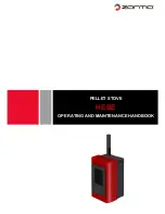
Figure 56 - Control Valve

LO HI

OFF

ON

PI

LO

T

Gas Control
Knob

Variable
Control Knob

Piezo
Ignitor

1.

After lighting, let pilot flame burn for about one minute.
Turn gas control knob on the control valve to ON position.
Turn variable control knob anywhere between HI and LO.
Slide the selector switch to the REMOTE position. 

Note:

The burners may light if hand-held remote ON button was
on when selector switch was last turned off. You can now
turn the burners on and off with either optional hand-held
remote control unit.

IMPORTANT:

 Do not leave the selector switch in the RE-

MOTE position when the pilot is not lit. This will drain the
battery.

IMPORTANT:

 Be sure to press the ON/OFF buttons on the

hand-held remote control unit for up to 3 seconds to assure
proper operation.

Note:

 All remote control accessories must be purchased sepa-

rately (See Accessories on page 39). Follow instructions in-
cluded with the remote control.

Thermostat Control Operation

(Optional CGHRCTA Only) The thermostat control setting on
the remote control unit can be set to any comfort level between
HI and LO. The burners will turn on and off automatically to
maintain the comfort level you select. The ideal comfort setting
will vary by household depending upon the amount of space to
be heated, the output of the central heating system, etc.

NOTICE: You must light the pilot before using the
hand-held remote control unit. See 

Lighting Instruc-

tions, page 24.

OPTIONAL REMOTE

OPERATION

OPERATING STOVE WITH BURNER SYSTEM

LIghting Instructions (Cont.)
To Turn Gas Off To Appliance
Manual Lighting Procedure
Optional Remote Operation

Summary of Contents for CDVBNC

Page 1: ...any other appliance FOR YOUR SAFETY WHAT TO DO IF YOU SMELL GAS Do not try to light any appliance Do not touch any electrical switch Do not use any phone in your building Immediately call your gas su...

Page 2: ...gases are odorless An odor making agent is added to the gas The odor helps you detect a gas leak However the odor added to the gas can fade Gas may be present even though no odor exists Make certain y...

Page 3: ...paper or other objects 13 Never place anything on top of stove 14 Do not use any solid fuels wood coal paper cardboard etc in this stove Use only the gas type indicated on burner system nameplate 15...

Page 4: ...TERMS PRE INSTALLATION PREPARATION Location and Space Requirements LOCATION AND SPACE REQUIREMENTS Determine the safest and most efficient location for your Comfort Glow cast iron stove Make sure tha...

Page 5: ...n and Space Requirements Cont 6 4 Front 4 36 from Front 42 Ceiling Floor Back Wall Figure 3 Clearances for Standard Installation 29 Must contain a minimum of 1 clearance to combustibles PRE INSTALLATI...

Page 6: ...ST IRON STOVE AND DIRECT VENT BURNER SYSTEM ASSEMBLY 8 Fasten each leg to stove with four 4 M8 x 1 25 20mm bolts Use a flat washer and lock washer with each bolt Tighten bolts into threaded holes on s...

Page 7: ...leveling after stove is in normal stand ing position 13 Carefully lift stove back up on its four attached legs 14 Set top grate into stove top CAST IRON STOVE AND DIRECT VENT BURNER SYSTEM ASSEMBLY Co...

Page 8: ...fit against the back of the burner system 2 Make sure all wire connections to terminals on blower motor and thermal switch where applicable are securely attached and that the screw retaining the green...

Page 9: ...y using the following guidelines Only use Comfort Glow or Simpson Dura Vent GS venting com ponents or kits specifically approved for this stove and burner system Minimum clearance between vent pipes a...

Page 10: ...side walk or a paved driveway located on public property 84 inches 2133mm minimum M clearance under veranda porch deck 12 inches 305mm minimum N clearance above a roof shall extend a minimum of 24 inc...

Page 11: ...this vent sys tem require a minimum clearance of 2 from the top of the pipe and 1 minimum to the sides and bottom Vertical sections of this system require a minimum of 1 clearance to combustible mate...

Page 12: ...s also available see page 18 Follow the same installation procedures used for standard horizontal terminations If installing the snorkel termination below grade basement applications you must provide...

Page 13: ...ening Combustible Wall Vent Opening Figure 23 Installing Horizontal Vent Cap Noncombustible Exterior Figure24 InstallingVinylSidingStandoff CombustibleExterior Interior Wall Surface Screw Vent Cap Hor...

Page 14: ...ntal Venting Vertical V Horizontal H 35 min 20 max Figure 27 Horizontal Termination Configuration for Rigid Venting Using One 90 Elbow Horizontal Venting Vertical V Horizontal H 42 min 32 max 30 elbow...

Page 15: ...t cap onto the last section of vent pipe and seal outer pipe connection with high temperature silicone seal ant as specified in the second warning statement on page 11 Note If the vent pipe passes thr...

Page 16: ...iling installation by following the same procedures outlined in steps 2 through 7 for Flat Ceiling Installation page 15 VENTING INSTALLATION Continued Vertical Termination Configurations Figures 34 an...

Page 17: ...ve at an elevation above 4500 feet in Canada check with local authorities Consultyourlocalgascompanytohelpdeterminetheproperorifice for your location For assistance with any high altitude installation...

Page 18: ...gas supply Follow all local codes CAUTION For propane LP units never connect burner system directly to the propane LP supply This burner system requires an external regulator not supplied Install the...

Page 19: ...ING Test all gas piping and connections for leaks after installing or servicing Correct all leaks at once WARNING Never use an open flame to check for a leak Apply a noncorrosive leak detection soluti...

Page 20: ...re Testing Burner System Gas Connections 1 Open equipment shutoff valve see Figure 41 2 Open propane LP supply tank valve for propane LP burner system or main gas valve located on or near gas meter fo...

Page 21: ...R SYSTEM INSTALLATION Installing Optional Wireless Hand held Remote Control Accessories CGHRC and CGHRCTA Series Removing Replacing Glass Door Figure 44 Removing Switch Plate LO H I P I L O T OFF ON F...

Page 22: ...rate see Figure 52 WARNING Failure to position the parts in accor dance with these diagrams or failure to use only parts specifically approved with this burner system may result in property damage or...

Page 23: ...Wait five 5 minutes to clear out any gas Then smell for gas including near the floor If you smell gas STOP Fol low B in the safety information above If you don t smell gas go to the next step 7 The p...

Page 24: ...th match 4 Keep gas control knob pressed in for 30 seconds after light ing pilot After 30 seconds release gas control knob Now follow steps 10 through 14 column 2 5 Replace glass door see Removing Rep...

Page 25: ...essory OPERATING STOVE WITH BURNER SYSTEM Continued Figure 57 Setting the Selector Switch Gas Control Knob and Variable Control Knob for Remote Operation ON OFF REMOTE LO H I OFF ON P I L O T Selector...

Page 26: ...SEMBLY The pilot assembly is factory preset for the proper flame height Alterations may have occurred during shipping and handling Call a qualified service person to readjust the pilot if necessary Th...

Page 27: ...eaning refer to Installing Logs Lava Rock and Glowing Embers page 23 to properly replace logs Use a vacuum cleaner to remove any carbon buildup on logs Replace log s if broken See Replacement Parts on...

Page 28: ...ty or partially clogged pilot 5 Thermocouple connection loose at con trol valve 6 Thermocouple damaged 7 Control valve damaged REMEDY 1 Reconnect ignitor cable 2 Free ignitor cable if pinched by any m...

Page 29: ...and let warm up for a minute 2 Operate burner until air is removed from line Have gas line checked by local pro pane LP or natural gas company 3 Clean burner see Cleaning and Maintenance page 28 or r...

Page 30: ...See Warning statement above 2 Control valve defective 1 Gas leak See Warning statement above 1 Improper log placement 2 Air holes at burner inlet blocked 3 Burner flame holes blocked OBSERVED PROBLEM...

Page 31: ...mm Weight lbs kg Burner System 70 lbs 31 8 kg 70 lbs 31 8 kg Shipping 75 lbs 34 kg 75 lbs 34 kg When installed in Comfort Glow cast iron stove body CISGA Series and CISCA Series REPLACEMENT PARTS Note...

Page 32: ...formation visit www desatech com 32 ILLUSTRATED PARTS BREAKDOWN CDVBNC CDVBPC LO H I P I L O T OFF ON 27 19 20 21 23 29 30 4 25 1 2 4 4 7 8 9 10 11 13 12 31 15 16 17 18 22 22 28 5 32 3 24 26 1 26 4 26...

Page 33: ...2 14 105468 01 Valve Bracket 1 15 14563 Valve Natural 1 14564 Valve Propane LP 1 16 14561 Pilot Assembly Natural 1 14562 Pilot Assembly Propane LP 1 17 102445 01 Ignitor Piezo 1 18 102334 01 Palnut Fa...

Page 34: ...rmation visit www desatech com For more information visit www desatech com 34 ILLUSTRATED PARTS BREAKDOWN STOVE CHASSIS CISC CISG 1 4 6 4 5 4 5 1 5 2 3 5 3 5 4 2 ILLUSTRATED PARTS BREAKDOWN Stove Chas...

Page 35: ...ttom 1 4 104970 01 One Leg Charcoal 4 Total Per Stove 1 104970 02 One Leg Forest Green 4 Total Per Stove 1 5 104971 01 Hardware Kit 1 5 1 Door Hinge Step Bolt With Shoulder 1 Per Unit 1 5 2 Door Catch...

Page 36: ...they can not supply these accessories call DESA International s Sales Department at 1 866 672 6040 for informa tion You can also write to the address listed on the back page of this manual MANUAL BLO...

Page 37: ...ted College Completed Graduate School 13 Age of Purchaser Under 20 20 29 30 39 40 49 50 59 60 or Over 14 Buyer s total annual household income Under 15 000 15 000 to 19 999 20 000 to 34 999 35 000 to...

Page 38: ...105501 01F For more information visit www desatech com For more information visit www desatech com 38 2701 Industrial Drive P O Box 90004 Bowling Green KY 42102 9004 TM Postage Required TAPE...

Page 39: ...105501 01F For more information visit www desatech com For more information visit www desatech com 39 39...

Page 40: ...l wear and tear or parts that fail or become damaged as a result of misuse accidents lack of proper maintenance or defects caused by improper installation Travel diagnostic cost labor transportation a...

Reviews: