background image

1

130112_Rev 2  GF 160 DV  2/22
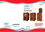
Jøtul GF 160 DV


Direct Vent Gas Stove

Installation and 

Operation Instructions

–  Do not store or use gasoline or other flammable 

vapors and liquids in the vicinity of this or any 

other appliance.

–  WHAT TO DO IF YOU SMELL GAS
  •  Do not try to light any appliance.
  •  Do not touch any electrical switch; do not 

use any phone in your building. 

• Leave the building immediately. 

• Immediately call your gas supplier from a 

neighbor’s phone.  Follow the gas supplier’s 

instructions.

  •  If you cannot reach your gas supplier, call the 

fire department.

–  Installation and service must be performed by 

a qualified installer, service agency or the gas 

supplier.

–  In the Commonwealth of Massachusetts, 

a carbon monoxide (CO) detector shall be 

installed in the same room as the appliance.

WARNING:  If the information in these 

instructions is not followed exactly, a fire or 

explosion may result causing property damage, 

personal injury or loss of life.

This appliance may be installed in an aftermarket, 

permanently located, manufactured home or mobile 

home, where not prohibited by local codes.
This appliance is only for use with the types of gas 

indicated on the rating plate.  A conversion kit is supplied 

with the appliance.

INSTALLER: Leave this manual with the appliance.
OWNER: Retain this manual for future reference.

!

A barrier designed to reduce the burn hazard 

from the hot viewing glass is provided with this 

appliance and must be installed for the protection 

of children and other at-risk individuals.

DANGER

!

HOT GLASS

 WILL 

CAUSE BURNS.

DO NOT TOUCH GLASS

UNTIL COOLED.

NEVER 

ALLOW CHILDREN 

TO TOUCH GLASS.

Certified to ANSI Z21.88-2019 • CSA 2.33-2019 
and CAN/CGA 2.17-M17.

Continuous Pilot Ignition

Summary of Contents for GF 160 DV

Page 1: ...tor shall be installed in the same room as the appliance WARNING If the information in these instructions is not followed exactly a fire or explosion may result causing property damage personal injury or loss of life Thisappliancemaybeinstalledinanaftermarket permanentlylocated manufacturedhomeormobile home wherenotprohibitedbylocalcodes Thisapplianceisonlyforusewiththetypesofgas indicatedontherat...

Page 2: ...icable a Product approved air intake must be used Installation shall be in strict compliance with the manufacturer s instructions A copy of the installation instructions must remain with the appliance or equipment at the completion of the installation 4 A Manual gas supply line shut off valve must be installed THIS OWNER S MANUAL PROVIDES INFORMATION TO ENSURE SAFE INSTALLATION AND EFFICIENT DEPEN...

Page 3: ... River Rocks 21 Tumbled Stones 21 Glass 21 Burner Flame Pattern References 22 Beach Fire Logset Installation 23 13 System Check 25 14 Flame Picture Adjustment 26 15 Operation Guidelines 27 16 Maintenance 28 Annual Cleaning 28 Glass Care Replacement 28 Safety Screen Replacement 30 17 Appendix 35 Illustrated Parts Lists 31 Mobile Home Requirements 35 18 Warranty Statement 36 19 Lighting Instructions...

Page 4: ...justment Washers 3 117587 GF 160 DV Manual 130112 Top Plate Grill 2 Matte Black 22299592 Options Accessories Log Set 158045 Beach Fire Logset 158229 Tumbled Stones 158054 River Rock Set 158055 Clear White Glass 156815 Black Glass 157342 Skamol Panel Set 158046 Black Reflective Panel Set 157965 Fuel Conversion Kit LP 158295 Fuel Conversion Kit NG 158293 High Altitude Adjustment Kit LP 158296 High A...

Page 5: ...or lower edge Lift the Top Plate Grills and Top Plate from the stove and set aside Note Reinstall Top Plate before installing venting Remove the Latch Tool from the shipping pallet and use it to remove the Glass Panel by pulling the two latch hooks out to disengage them from the glass frame Fig 2 2 Tilt the glass frame forward then lift it straight up and off of the stove 2 Remove the Miscellaneou...

Page 6: ...a qualified service technician to inspect the heater and to replace any part of the control system and any gas control which may have been under water 4 Safety Information Due to the high operating temperatures this appliance should be located out of traffic and away from furniture and draperies Maintain proper clearance to combustible mantels and fireplace trim Children and adults should be alert...

Page 7: ...officials Remember Fire Resistant materials are considered combustible they are difficult to ignite but will burn Also fire rated sheet rock is considered combustible Floor Protection This appliance MAY NOT be installed directly on carpeting vinyl or linoleum If this appliance will be installed on any combustible material OTHER THAN WOOD a floor pad must be installed that is either metal wood cera...

Page 8: ...imum Alcove Ceiling Height from floor 69 Alcove clearances are determined through testing in specific construction configurations which often result in greater clearances than an open stove installation Clearance to Combustible Materials Above Stove Minimum Mantle Height from floor 46 3 4 with 24 maximum mantle depth Figure 5 4 Alcove Clearances ...

Page 9: ...re Seal Direct Vent Industrial Chimney Corp ExcelDirect Bernard Dalsin Mfg Pro Form Olympia Chimney Supply Inc Ventis Direct Vent Use parts of one manufacturer only DO NOT MIX VENT COMPONENTS FROM DIFFERENT MANUFACTURERS IN THE SAME SYSTEM Installation of any components not manufactured or approved by Jøtul or failure to meet all clearance requirements will void all warranties and could result in ...

Page 10: ...k Nut Approved Horizontal and Vertical Vent Terminations ALL VENTING MUST TERMINATE END WITHIN ONE OF THE DESIGNATED AREAS SET STOVE EXHAUST RESTRICTOR TO THE POSITION THAT CORRESPONDS TO THE VENT TERMINATION AREA IN THE MATRIX When termination is exactly on a division line use the less restrictive position For example if termination is 10 feet high and offset 7 feet restriction should be set at P...

Page 11: ...attic space must be retained by an insulation barrier Horizontal Overhang Vertical Wall Termination Cap 18 min Lowest Discharge Opening 18 min 18 min Figure 6 5 Vertical vent termination height above roof NOTE FOR CO LINEAR INSTALLATIONS WHEN LIGHTING THE APPLIANCE FOR THE FIRST TIME AFTER REMOVING THE FRONT GLASS YOU WILL NEED TO LIGHT PILOT AND LEAVE UNIT FOR 10 15 MINUTES TO ALLOW FOR DRAFT TO ...

Page 12: ...potential heat damage to the siding SNORKEL TERMINATION HORIZONTAL RUN MUST NOT EXCEED 2 FEET 61 CM A 14 356mm or 36 914mm snorkel termination is approved in conformance with the vent rise run and termination clearance specifications published in this manual See figs 6 9 6 10 The snorkel termination must comply with grade and building clearance requirements per local and national building codes 45...

Page 13: ...hin a height 15 ft above the meter regulator assembly I Clearance to service regulator vent outlet 3 ft 91 cm J Clearance to nonmechanical air supply inlet to building or the combustion air inlet to any other appliance 12 in 30 cm 9 in 23 cm K Clearance to a mechanical air supply inlet 6 ft 1 83 m 3 ft 91 cm above if within 10 ft 3 m horizontally L Clearance above paved sidewalk or paved driveway ...

Page 14: ...oor and push the stem back far as it will travel See fig 7 1 4 Remove the Burner Lift the front of the burner base to disengage it from the support brackets and pull it forward off of the burner injector Then tilt it side to side and pull it out through the door opening Fig 7 2 5 Change the Burner Injector See fig 7 3 Using a 1 2 open end wrench or deep well socket remove the burner injector from ...

Page 15: ...emove Pilot Shield Figure 7 3 Injector and Pilot conversion The LP shutter lock screw sets the minimum shutter opening for propane INSTALLER NOTE Pilot Shield is removed for PROPANE in a Minimum Vent Run For taller vent configurations or where high winds are present the shield can remain installed if nuisance outages are experienced Keep the Pilot Shield for potential future replacement ...

Page 16: ...k Check Check for leaks using a soapy water solution or digital gas detector NEVER USE OPEN FLAME TO CHECK FOR GAS LEAKS 15 Confirm correct gas pressure Use a manometer to check pressures as specified under Section 9 Gas Pressure page 19 Figure 7 4 Upper Baffle LP conversion Exhaust Baffle Upper Baffle Remove Upper Baffle wings Figure 7 4a Break off the Upper Baffle wings LP conversion Apply Label...

Page 17: ...N MASSACHUSETTS TO COMPLY WITH CODE 248CMR Secure all joints tightly using appropriate tools and sealing compounds For propane units be sure to use compounds that are propane resistant Turn on gas supply and test for gas leaks at all joints Figure 8 1 Gas supply line connection alternatives Fuel Conversion cont d 16 NATURAL GAS ONLY Adjust the Air Shutter Fig 7 10 The factory setting for NG is 1 1...

Page 18: ...r use at elevations above 2000 feet Check with your gas supplier before performing derate adjustment to the burner If the gas supplier does not derate fuels install High Altitude Adjustment Kit 158059 for Propane and Kit 158060 for Natural gas U S Canada per ANSI Z21 88 2019 CSA 2 33 2019 CAN CGA 2 17 Orifice Sizes for 610 1370 meters 2000 4500 ft Natural Gas 2 30 mm Propane 1 40mm See data on the...

Page 19: ... Set a panel in place against the firebox wall and use a flat head screwdriver to pry the retainer tab down just enough to hold the panel snug in place 3 Repeat with the other side panel INSTALL FUEL OR HIGH ALTITUDE CONVERSION KITS BEFORE INSTALLING PANEL KITS Reflective Black Glass Contents Rear Panel 226073 Left Side Panel 226075 Right Side Panel 226074 Cotton Gloves 2 Skamol Panel Contents Rea...

Page 20: ...hole in the charred end of the Left Log 3 with the Base Log pin and lean it up against the back corner of the firebox See figs 12 1 and 12 2 4 If desired spread the Ember Stones over the Burner Base in a thin layer DO NOT COVER GAS PORTING HOLES ON THE SIDES OR FRONT OF THE BURNER PLACE STONES OVER THE REAR PORTS ONLY AND UP TO THE REAR FLANGE OF THE BURNER KEEP EMBER STONES AWAY FROM THE PILOT CA...

Page 21: ...es do not completely block gas flow through the ports in a single layer Also DO NOT OBSTRUCT THE AIR SPACE BETWEEN THE BURNER PERIMETER AND THE BURNER SKIRT See fig 12 4 Clear White Fire Glass 156815 Black Fire Glass 157342 Do not use more than the four pounds in two 2 lb bags of glass media provided For best results evenly spread the contents of the bag over the entire burner plate mounding a cro...

Page 22: ...22 130112_Rev 2 GF 160 DV 1 22 Burner Reference Flame Patterns Figure 17 7 Rock Set flame pattern Figure 17 8 Tumbled Stone flame pattern Figure 17 9 Fire Glass flame pattern ...

Page 23: ...re in the lower ends of logs 5 and 6 LOG IDENTIFICATION 1 2 3 4 5 6 A B C C D E PIN IDENTIFICATION A 2 Install the Adaptor Plate 1 on the burner by engaging it with the two burner pins A at the arrows shown above 3 Loosely spread a layer of ember stones around the perimeter of the burner plate 3 2 4 4 Engage the holes in the bottom of Rear Log 2 with the two steel pins B at the left rear corner of...

Page 24: ... hole at the lower end of the Left Vertical log 5 with left Adaptor pin A See Step 2 photo 8 Engage the hole at the lower end of the Right Vertical log 6 with pin E on the Adaptor plate Rest the upper end against the depression on the log 5 as shown ...

Page 25: ...ED PROFESSIONAL SERVICE TECHNICIAN INITIAL FIRING PROCESS Heat curing the Stove Paint This appliance has been painted with the highest quality coating used in the hearth industry Manufacturers have selected this product because it has been proven durable colorfast and beautiful at temperatures up to 1200 F 650 C Although the paint has been air dried at the factory it must be heat cured in order to...

Page 26: ...the air inlet shutter has been set to provide optimal combustion efficiency under a variety of venting configurations The air shutter may be adjusted however to accommodate the conditions of your individual installation and to provide the desired flame picture Other installation related variables can also affect the flame picture Too large an air setting the appliance will generate a flame that is...

Page 27: ...vapors 6 CAUTION DO NOT OPERATE THIS APPLIANCE WITH ANY OF THE GLASS PANELS REMOVED CRACKED OR BROKEN REPLACEMENT OF THE GLASS SHOULD BE DONE ONLY BY A LICENSED OR QUALIFIED SERVICE PERSON USE ONLY REPLACEMENT GLASS PROVIDED BY YOUR AUTHORIZED JØTUL DEALER NEVER SUBSTITUTE ANY OTHER TYPE OF GLASS REMOVE GLASS ONLY FOR ROUTINE MAINTENANCE ALWAYS HANDLE GLASS CAREFULLY WARNING READ AND UNDERSTAND AL...

Page 28: ...nd debris Vacuum more frequently if there are pets in the home Use a soft brush attachment and handle log set components carefully The pilot assembly and burner base should be inspected and cleaned annually by a qualified technician Replace any component showing evidence of corrosion Glass and Gasket Inspection It is important that the glass gasket be inspected at least annually Examine the ribbon...

Page 29: ...ig 17 2 from the firebox with removal of two 10 mm hex nuts 11 See also Fig 7 3 page 16 6 Remove the Glass Panel Remove the M6 hex bolt from the upper bracket strap at the top of the firebox Fig 16 2 Refer to fig 16 3 and fig 17 2 to locate the M8 hex bolt 7 that attaches the cast iron Side Plate to the stove Base Plate 40 Use the 13 mm socket with 24 inch extension to loosen but not remove the M8...

Page 30: ...reen and frame installs as a single unit using the original four brackets and screws Readjust and tighten the air shutter following the guidelines in Section 14 Air Shutter Adjustment on page 24 11 Replace the front Front Glass Frame and Top Plate Side Safety Screen Replacement Kit 158063 Read through these instructions before beginning the procedure Tool List 13mm socket 24 in socket extension sm...

Page 31: ... 14 15 16 17 17 6 18 19 6 17 6 20 21 6 22 23 24 7 25 11 26 27 28 29 30 31 7 7 32 34 35 6 36 6 11 79 4 5 6 6 37 38 39 11 11 7 40 11 42 43 44 45 46 47 48 49 50 51 52 53 15 1 59 60 1 61 62 15 63 15 63 1 1 70 71 72 73 74 66 78 11 39 38 37 11 78 Figure 17 2 GF 160 DV Firebox and Cast Iron Assembly 17 Appendix ...

Page 32: ...951 Wire Strain Relief Heyco 7P 2 Large 36 22605092 Rear Cover Supply Lines Matte Black 37 158080 Glass Ceramic Side 5mm 197 INC Gasket 38 38 225961 Gasket Woven Tape 187 x 750 39 22595492 Retainer Side Glass Matte Black 40 158068 Base Plate Matte Black 41 22595192 Glass Frame Matte Black 42 222280 Gasket Drop In Orifice Holder 43 226247 Shim Drop in Orifice Holder 44 223231 Orifice Holder Drop In...

Page 33: ... plain 11 226960 Controls Compartment GF160 DV 12 118034 Screw M6 x 12 Button Head Hex Socket Blk Oxide 13 117588 Washer Hinge M6 12mm OD x 6mm ID x 0 5mm Zinc 14 22605992 Control Door Matte Black 15 117921 Screw Pan Head Phillips M4 X 14 Blk Oxide 16 129154 Terminal Block 2 Pole 77 series 17 117922 Nut Hex M4 DIN 934 Plain 18 226959 Bracket Burner Switch GF160 DV 19 129153 Switch Rocker SPDT Blac...

Page 34: ...26075 Reflective Panel Left No Part No Description 1 158067 Replacement Glass Kit GF 160 DV IPI Does not include 2 Steel Glass Frame 2 22595192 Glass Frame 3 129124 Gasket Tadpole 25 x 1 25 7ft 4 225959 Glass Panel Ceramic 5 mm 5 220042 Tinnerman Retainer Clips 4 Figure 17 5 GF 160 DV Glass Assembly GF 160 Optional Panel Replacement Parts GF 160 Safety Screen Barrier Replacement 1 158062 Front Pan...

Page 35: ... 24 CFR PART 3280 THIS APPLIANCE IS ONLY FOR USE WITH THE TYPE OF GAS THAT IS INDICATED ON THE STOVE S RATING PLATE A GAS CONVERSION KIT IS PROVIDED WITH THE GF 160 DV GAS STOVE THIS APPLIANCE MAY BE INSTALLED IN AN AFTERMARKET PERMANENTLY LOCATED MANUFACTURED MOBILE HOME WHERE NOT PROHIBITED BY LOCAL CODES Figure 17 6 Floor Bracket installation Leg Bracket Kit 158074 Kit Contents Leg Bracket Two ...

Page 36: ...tions not in conformance with the installation instructions contained in this owner s manual or local and or national fire and building regulations 3 Damage due to service performed by an installer service agency or gas supplier unless otherwise agreed to in writing by JØTUL 4 Labor or other costs associated with the repair of gas controls plumbing burners log set lamp bulbs or sheet metal firebox...

Page 37: ...37 130112_Rev 2 GF 160 DV 2 22 This page is intentionally left blank ...

Page 38: ...38 130112_Rev 2 GF 160 DV 1 22 This page is intentionally left blank ...

Page 39: ...G INSTRUCTIONS WARNING IF YOU DO NOT FOLLOW THESE INSTRUCTIONS EXACTLY A FIRE OR EXPLOSION MAY RESULT CAUSING PROPERTY DAMAGE PERSONAL INJURY OR LOSS OF LIFE A This appliance has a pilot which must be lit by hand When lighting the pilot follow these instructions exactly B BEFORE LIGHTING smell all around the appliance area for gas Be sure to smell next to the floor because some gas is heavier than...

Page 40: ...s January 2021 130112 Rev 1 Your stove has a unique serial number stamped on the rating plate located in the control compartment Please record the serial number in the space below You may also wish to attach your purchase receipt to this page for future reference MODEL NAME Jøtul GF 160 DV SERIAL NUMBER _______________________________ DATE OF PURCHASE ____________________________ AUTHORIZED DEALER...

Reviews: