Dentsply Sirona CEREC Primemill Operating Instructions Manual Download Page 19

Dentsply Sirona
Operating Instructions CEREC Primemill

5 Installation and startup

5.3 Installation site

67 19 681 D3439
D3439.201.01.01.02    09.2019

19

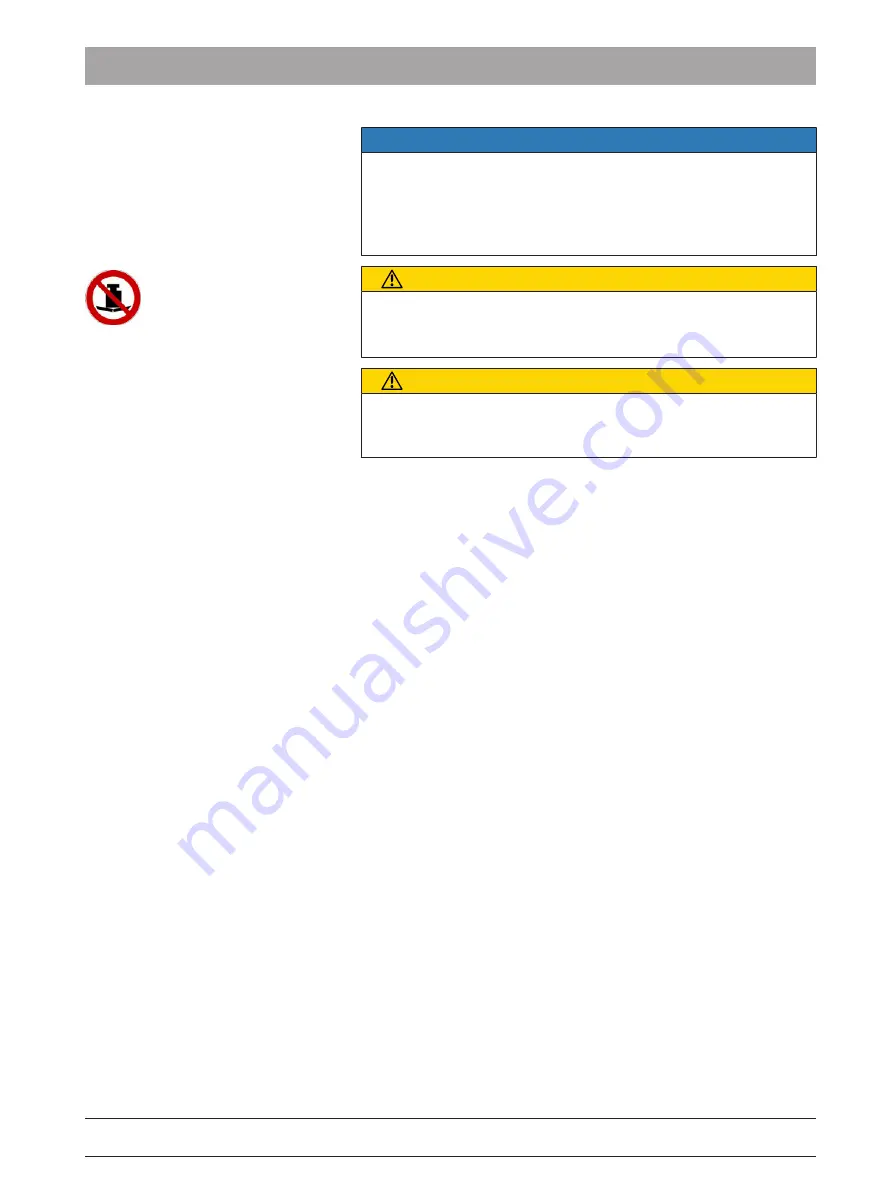
NOTE

Installation in a cabinet

If the unit is installed in a cabinet, you must provide for adequate heat
exchange.

The ambient temperature surrounding the unit must be between 5 °C
(41 °F) and 40 °C (104 °F).

CAUTION

Risk of injury and damage to the unit

The unit can be tilted when the drawer is extended.
➢ Install the unit so that the front does not project beyond the base.

CAUTION

Risk of injury and damage to the unit

Avoid tilting the unit. Do not lean against the pulled-out drawer and do
not apply a vertical load of more than 5 kg onto the pulled-out drawer.

Summary of Contents for CEREC Primemill

Page 1: ...New as of 09 2019 CEREC Primemill Operating Instructions not valid for USA English...

Page 2: ...o the product 12 4 1 4 Accessories and consumables 13 4 2 Opening the processing chamber door during the machining process 13 4 3 Electrostatic charge 13 4 3 1 ESD warning labels 13 4 3 2 ESD protecti...

Page 3: ...oint 32 5 4 6 7 Connecting to the PC via the wireless interface optional 32 5 4 7 Filling the water tank 34 5 4 8 Switching the unit ON and OFF 35 5 5 Repacking 36 5 6 Scope of supply 36 5 7 Storage 3...

Page 4: ...7 6 Cleaning surfaces 56 7 6 1 Disinfecting 56 7 6 2 Cleaning 56 7 7 Replacing the main fuses 57 7 8 Changing the filter 58 7 8 1 Procedure for all materials 59 7 9 Removing water from the unit 59 7 9...

Page 5: ...ards and cause damage Please therefore read and follow these operating instructions carefully Always keep them within easy reach Also pay attention to the safety instructions to prevent personal injur...

Page 6: ...ial damage please observe the warning and safety information provided in these operating instructions Such information is highlighted as follows DANGER An imminent danger that could result in serious...

Page 7: ...action step 2 Second action step or Alternative action Result Individual action step Requests you to do something See Formats and symbols used 7 Identifies a reference to another text passage and spec...

Page 8: ...06 based on IEC 60601 1 2005 EN 60950 1 2006 based on IEC 60950 1 2005 UL 60950 second edition 2010 RoHS compliance This symbol indicates that this product does not contain any toxic or hazardous subs...

Page 9: ...mpaired For the USA only CAUTION According to US Federal Law this product may be sold only to or by instruction of physicians dentists or licensed professionals Dry processing CAUTION In the event of...

Page 10: ...door during the machining process 13 This symbol can be found on the rating plate on the unit Meaning ESD warning sign see section Electrostatic charge 13 This symbol can be found on the drawer of th...

Page 11: ...9 D3439 201 01 01 02 09 2019 11 Symbols on the packaging Take note of the following symbols on the packaging Top Protect from moisture Fragile handle with care Stack limit Temperature during storage a...

Page 12: ...ted to open the unit with tools 4 1 2 Maintenance and repair As manufacturers of dental instruments and laboratory equipment we can assume responsibility for the safety properties of the unit only if...

Page 13: ...and grinding units in the downloads area at https my cerec com These lists are updated from time to time 4 2 Opening the processing chamber door during the machining process CAUTION Instruments that c...

Page 14: ...harges 14 4 3 3 About the physics of electrostatic charges What is an electrostatic charge An electrostatic charge is a voltage field on and in an object e g a human body which is protected against co...

Page 15: ...to plugs leading outside of the unit via cables are sensitive to electrostatic discharge Even voltages which are imperceptible to the user can cause breakdown of the structures thus leading to a disch...

Page 16: ...Sirona has selected the best possible configuration for data communication via the wireless interface CEREC Radio Device or WLAN which generally ensures perfect functioning of this connection However...

Page 17: ...please contact your carrying agent If return shipment is required please use the original packaging for shipment The unit must be drained before it is ever transported if it has been in operation see...

Page 18: ...nt place it at least 1 5 m away from the patient The production unit requires a level base of approx 729 mm x 465 mm W x D The height of the production unit is with the processing chamber door closed...

Page 19: ...at exchange The ambient temperature surrounding the unit must be between 5 C 41 F and 40 C 104 F CAUTION Risk of injury and damage to the unit The unit can be tilted when the drawer is extended Instal...

Page 20: ...201 01 01 02 09 2019 5 4 Commissioning NOTE Important information on initial startup Observe the software installation instructions 5 4 1 Functional elements Unit overview B A F E D C H G Production...

Page 21: ...startup 5 4 Commissioning 67 19 681 D3439 D3439 201 01 01 02 09 2019 21 Ports on the back side D E G F H B C A Connections A Main switch I ON 0 OFF E LAN B Fuse cover F USB B C Power connection G USB...

Page 22: ...rona Operating Instructions CEREC Primemill 22 67 19 681 D3439 D3439 201 01 01 02 09 2019 Processing chamber D F G E A B B A C Processing chamber A Instrument set 1 E Motor mount B Instrument set 2 F...

Page 23: ...Calibrating the unit 38 5 4 2 3 Torque wrench To insert or replace the instruments or calibration pins use the appropriate torque wrench When doing so pay attention to the connection geometry of the t...

Page 24: ...constant Starting position White pulsating White pulsating Yellow constant Complete White constant White constant Green constant Errors Red constant Red constant Green constant The unit is ready to r...

Page 25: ...ves to starting position White constant White constant Yellow constant Off Off Blue constant 5 4 5 Using the processing chamber screen NOTE Risk of blockage in the cooling circuit If chips enter into...

Page 26: ...rmed before putting the unit into operation 5 4 6 3 1 Process steps that have to be taken on the unit The unit is connected to a power supply source and the main switch on the rear of the unit is swit...

Page 27: ...display Manual unit search The unit is connected to the PC via a LAN cable or via WLAN 1 Click the Configuration button in the system menu 2 Click on the Devices button 3 Click on the Add Device Manu...

Page 28: ...e suction tube to the available connection point on the suction device A 2 Connect the other end of the tube to the rear side of the production unit B Notes on the suction tube The suction tube is sup...

Page 29: ...he other end into an appropriate power socket with a protective ground terminal Note on the power cable The suction system must only be operated with a power cable with a plug system designed for the...

Page 30: ...ction unit monitors the correct connection interface cable and suction tube and the operation of the suction system during the running processes 5 4 6 4 5 Setting the suction power Use the control dia...

Page 31: ...ure mode chapter Final work analyzing connection quality If applicable follow the instructions on changing channels 3 After you have found the optimum setting take the acquisition unit and place it in...

Page 32: ...ow all production units connected to the LAN switch can be operated via WLAN 5 4 6 7 Connecting to the PC via the wireless interface optional The CEREC acquisition unit has one of the following wirele...

Page 33: ...LED displays in the CEREC Radio Device operating instructions REF 65 45 177 All network devices now belong to a single network which can be operated as an independent network and can communicate with...

Page 34: ...ert hard to open by hand use the tank cap opener see Using the tank cap opener NOTE Coolant Use distilled or demineralized water Water tank A Tank D Tank drain B Tank cap E RFID label RFID tag C Filte...

Page 35: ...x 10 seconds 13 Switch the water pump component off 14 Fill the water tank up again until the filter insert is completely immersed up to the bottom edge of the cap thread 15 Select the symbol shown on...

Page 36: ...n changes from green to blue 5 5 Repacking NOTE Repack only drained units Drain the unit The water tank is empty The main switch on the back side of the unit is set to the 0 OFF position 1 Disconnect...

Page 37: ...ration pins instruments In the event of cleaning or maintenance work in the processing chamber we recommend removing the instruments Bur 1 0 and or Bur 0 5 beforehand We also recommend that you select...

Page 38: ...on phantom when calibrating the unit Unit calibrated ex works The unit is calibrated at the factory No additional calibration is required during initial startup Proceed as described below when perform...

Page 39: ...m in the machine 6 Close the door The calibration for set 1 is performed The automatic calibration starts and lasts approx 4 minutes Wait until the calibration has been completed 7 Remove the calibrat...

Page 40: ...dues Remove the restored objects and material residues carefully after the processing Pay attention to the sharp edged material residues while cleaning the processing chamber Different process types a...

Page 41: ...rconium oxide wet and dry Yellow Square Bur 1 0 CS 6713932 All purpose milling wet and dry Black Triangular Bur 0 5 CS 6713924 All purpose milling wet and dry Black 6 3 1 3 Permitted instrument combin...

Page 42: ...ze color and enlargement factor of the block 3 Open the door 4 Place the selected block in the block fixing 5 Clamp the block with the ball pressure screw Use the block clamp tool for this purpose see...

Page 43: ...asp the remainder of the ceramic block by its metal holder 3 Loosen the ball pressure screw 4 Remove the remainder of the ceramic block When removing the remaining block from blocks with 6 mm diameter...

Page 44: ...ceramic breakages Securely tighten the block with the block clamping tool with the torque wrench until you can hear a clicking sound Check to make sure that the block is seated very firmly 1 Insert t...

Page 45: ...mm diameter block holders NOTE Fasten the block tightly If the block is not sufficiently tightened it can lead to unsuitable results and ceramic breakages Securely tighten the block with the block cl...

Page 46: ...gineer NOTE Machine care Interval Once a week or after every 4th water change Change the filter see Changing the filter Clean manual block fixing with the supplied tool A Also clean instrument clampin...

Page 47: ...available separately as a spare part REF 65 89 795 We recommend carrying out this cleaning procedure or the wet milling of a restoration at least once per week if the device is used for dry milling of...

Page 48: ...a notification to change the filter bag of the CEREC suction system after 120 dry milled restoration units This number may differ depending on the amount of zirconium oxide materials milled and sucti...

Page 49: ...onium oxide materials milled and suctioned If the HEPA filter is full before the notification the touch display might display a warning at low pressure meaning that the HEPA filter needs to be replace...

Page 50: ...insert a new HEPA filter 7 Put the perforated sheet back on and screw it down with the two Phillips screws 8 Put the filter bag back on again 9 Put the maintenance cover on and screw it down with the...

Page 51: ...nge the water at least once a week With ambient temperatures above 25 C 77 F change the water every 2 to 3 days to prevent foul odors Drain the tank if you do not intend to operate the unit for more t...

Page 52: ...memill 52 67 19 681 D3439 D3439 201 01 01 02 09 2019 7 3 2 Changing the water NOTE Change the filter insert regularly Replace the filter insert with a new one on every fourth water change at the lates...

Page 53: ...he drain opening D 9 Turn the tank cap B counter clockwise and take it off NOTE Foaming not permissible If any cleaning agents are used this will create foam which is not permitted Do not use any clea...

Page 54: ...leaning Position option on the touch display to position the motors together so that the floor of the production chamber is easier to access and to clean A dialog box is displayed on the touchscreen w...

Page 55: ...he touch display is displayed in red The touch display also offers the option of replacing the defective instrument A dialog box is displayed on the touchscreen which specifies the instrument to be ch...

Page 56: ...pro Plasti Sept Plasti Sept Wipes Henry Schein Maxima Non Alcoholic Surface Disinfection Sch lke Mayr Mikrozid Sensitive Liquid Mirkozid Sensitive Wipes D rr FD 366 Sensitive FD 366 Sensitive Wipes Ke...

Page 57: ...unit end before replacing the fuses NOTE Fuse type Use only fuses of the same type in the fuse holder Fuse holder A Cover C Fuse holder B Main switch D Fuse Fuses T3 15H250V Order no 64 45 378 The po...

Page 58: ...hange the filter insert regularly Replace the filter insert with a new one once per week or on every fourth water change You must also replace with a new filter cartridge when the water pressure is to...

Page 59: ...lter unit 1 pcs 63 87 067 Filter unit six pack 64 29 950 7 9 Removing water from the unit You must remove water from the unit if you will not be using it for a long period of time or wish to transport...

Page 60: ...nly for opening the tank cap Do not use the tank cap opener for closing the tank cap It is sufficient to tighten the tank cap clockwise by hand Opening the tank cap The water tank has been pulled out...

Page 61: ...Lab CAM SW 21 0 and higher versions 8 2 Production unit 8 2 1 General technical description Digital feed control with force monitoring for extremely sensitive processing Process controlled tool drives...

Page 62: ...ection against ingress of water Ordinary device without pro tection against ingress of wa ter Overvoltage category II Ambient conditions For indoor use Pollution degree 2 Air pressure 700 hPa 1060 hPa...

Page 63: ...return of the electrical device please send a disposal request to enretec GmbH You have the following options here Use the Returning an electrical device button under the eom menu item on the enretec...

Page 64: ...ding White Diamond 1 0 CS 6714062 Grinding White Diamond 0 6 CS 6714054 Grinding White Instrument REF Usage Color Connection geometry of the force transmission Bur 2 5 ZrO2 CS 6713940 Milling of zirco...

Page 65: ...ignation Illustration 6718410 Block clamp tool spare part 6479856 HT torque wrench spare 6479849 Torque wrench spare 6623792 Adapter sleeve 6704790 Adapter sleeve removal tool 6718444 Calibration set...

Page 66: ...ona Operating Instructions CEREC Primemill 66 67 19 681 D3439 D3439 201 01 01 02 09 2019 REF Designation Illustration 6718469 Screen insert spare part 6429950 Filter MC MCX pack of 6 units 6151562 10...

Page 67: ...nt 56 Disposal of old electrical and electronic devices 63 E enretec GmbH 63 F Filter mode 58 Order number 59 Fuse 21 Fuse type 57 Order number 57 Replacement 57 H Humidity range 62 I Installation sit...

Page 68: ...01 02 09 2019 S Safety instructions 6 Scope of supply 36 T Temperature range 62 Transport 17 Type designation 62 U Unpacking 17 V Ventilation slots 16 W Water 62 Water tank Changing the water 53 Fill...

Page 69: ......

Page 70: ...be required due to technical improvements Sirona Dental Systems GmbH Sprache englisch Printed in Germany D3439 201 01 01 02 09 2019 Nr 000 000 Sirona Dental Systems GmbH Fabrikstr 31 64625 Bensheim G...

Reviews: