background image

ENGLISH

9

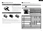
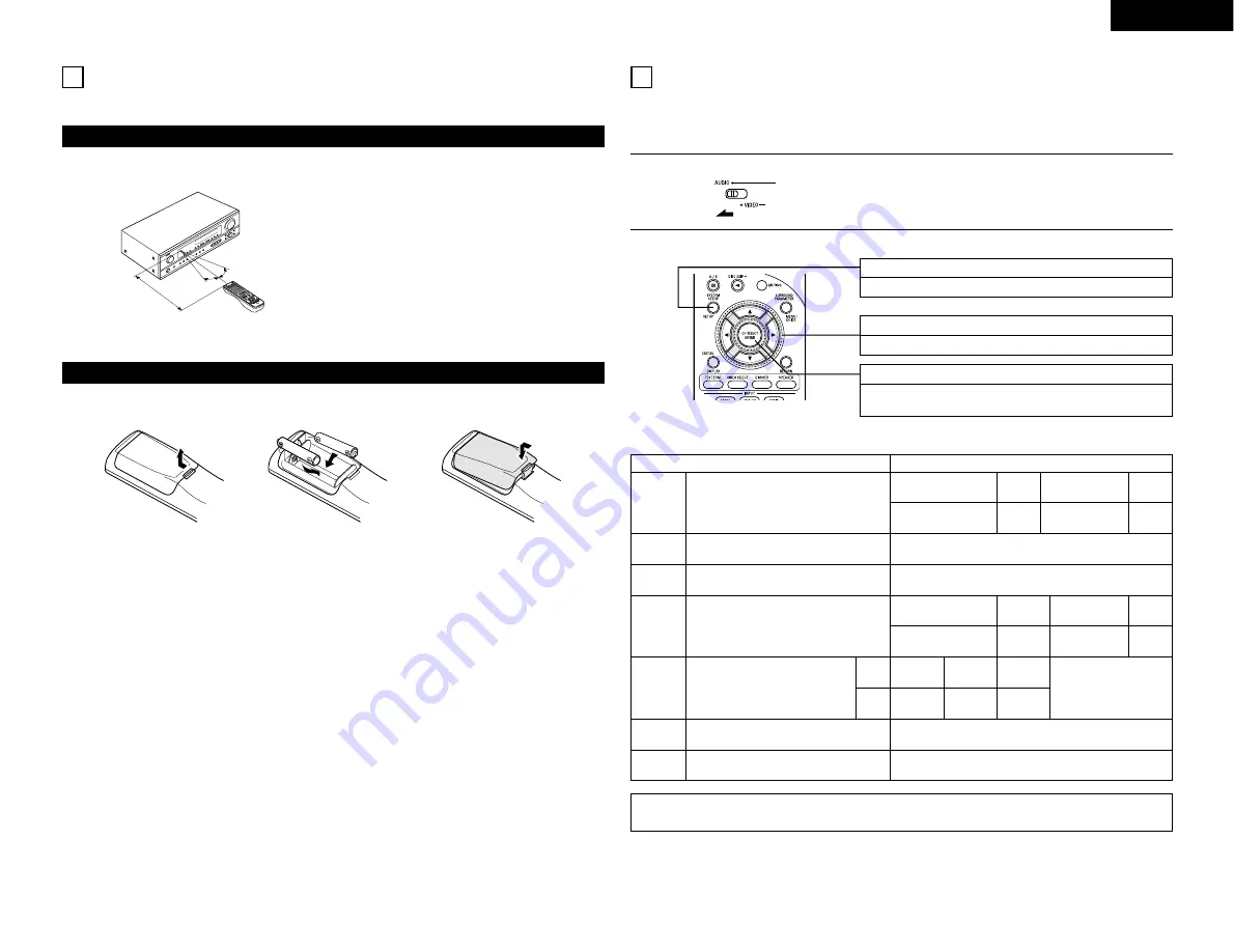
Following the procedure outlined below, insert the batteries before using the remote control unit.

Point the remote control unit at the remote control
sensor as shown on the diagram at the left.

NOTES:

• The remote control unit can be used from a straight

distance of approximately 7 meters, but this distance
will shorten or operation will become difficult if there
are obstacles between the remote control unit and
the remote control sensor, if the remote control
sensor is exposed to direct sunlight or other strong
light, or if operated from an angle.

• Neon signs or other devices emitting pulse-type noise

nearby may result in malfunction, so keep the set as
far away from such devices as possible.

Approx. 7 m

q

Press as shown by the arrow
and slide off.

w

Insert the R6P/AA batteries properly,
as shown on the diagram.

e

Close the lid.

NOTES:

• Use only R6P/AA batteries for replacement.
• Be sure the polarities are correct. (See the illustration inside the battery compartment.)
• Remove the batteries if the remote control transmitter will not be used for an extended period of time.
• If batteries leak, dispose of them immediately. Avoid touching the leaked material or letting it come in contact

with clothing, etc. Clean the battery compartment thoroughly before installing new batteries.

• Have replacement batteries on hand so that the old batteries can be replaced as quickly as possible when the

time comes.

• Even if less than a year has passed, replace the batteries with new ones if the set does not operate even when

the remote control unit is operated nearby the set. (The included battery is only for verifying operation.
Replace it with a new battery as soon as possible.)

30°

9 USING THE REMOTE CONTROL UNIT

Range of operation of the remote control unit

Inserting the batteries

30°

10 SETTING UP THE SYSTEM

• Once all connections with other AV components have been completed as described in “CONNECTIONS” (see

pages 5 to 8), make the various settings described below on the display.
These settings are required to set up the listening room’s AV system centered around the this unit.

SYSTEM SETUP button

Press this to display the system setup on the display.

CURSOR buttons (

ª

0

1

)

Press this change what appears on the display.

ENTER button

Press this to switch the display.
Also use this button to complete the setting. 

• System setup items and default values (set upon shipment from the factory)

Input the combination of speakers in your system and

their corresponding sizes (SMALL for regular speakers,

LARGE for full-size, full-range) to automatically set the

composition of the signals output from the speakers and

the frequency response.

Front Sp.

Center

Sp.

Surround Sp.

Subwoofer

Large

Small

Small

Yes

System setup

Speaker

Configuration

This selects the subwoofer speaker for playing deep bass

signals.

This parameter is for optimizing the timing with which

the audio signals are produced from the speakers and

subwoofer according to the listening position.

Subwoofer

Mode

Delay Time

Default settings

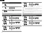
Set the slide switch to “AUDIO”.

1

Use the following buttons to set up the system:

2

Subwoofer mode = Normal

Front & Subwoofer

Center

Surround L & R

3.6 m

3.6 m

3.0 m

NOTE:

• The system setup is not displayed when “HEADPHONE ONLY” is selected.

Digital

Inputs

Input

source

Digital In

Assignment

This assigns the digital input jacks for the

different input sources.

COAXIAL

CD

OPTICAL-1

OPTICAL-2

DVD/VDP

TV/DBS

Set the frequency (Hz) below which the bass sound of

the various speakers is to be output from the subwoofer.

Crossover

Frequency

80 Hz

Auto surround mode function setting.

Auto Surround

Mode

Auto Surround Mode = ON

Set the Ext. In Subwoofer channel playback level.

Ext. In SW

Level

Ext. In SW Level = +15 dB

Summary of Contents for DHT-483XP

Page 1: ...ITALIANO PAGINA 02 84 PAGINA 110 192 PARA LECTORES DE ESPA OL PAGINA 2 111 PAGINA 137 192 VOOR NEDERLANDSTALIGE LEZERS PAGINA 2 138 PAGINA 164 192 FOR SVENSKA L SARE SIDA 2 165 SIDA 192 AV SURROUND RE...

Page 2: ...yentes con el equipo Laat geen insektenverdelgende middelen benzine of verfverdunner met dit apparaat in kontakt komen Se till att inte insektsmedel p spraybruk bensen och thinner kommer i kontakt med...

Page 3: ...ispersal leave at least 10 cm of space between the top back and sides of this unit and the wall or other components Switching the input function when input jacks are not connected A clicking noise may...

Page 4: ...D button 24 5 EXT IN button 16 17 6 SIGNAL indicators 16 7 INPUT mode indicators 16 8 Remote control sensor REMOTE SENSOR 9 9 Power operation indicator ON STANDBY 0 INPUT SELECTOR knob 16 18 19 24 26...

Page 5: ...is used independently without turning the power of this unit on If this happens turn on the power of this unit Connecting the audio components 1 Decoders with 6 channel analog outputs etc Connecting...

Page 6: ...VDP can also be connected to the VCR terminals AUDIO VIDEO Connecting a video decks Connecting a TV DBS tuner TV DBS Connect the TV s or DBS tuner s video output jack VIDEO OUTPUT to the yellow TV DB...

Page 7: ...VIDEO OUT S VIDEO OUT IN S VIDEO VIDEO IN VIDEO OUT VIDEO IN VIDEO OUT VIDEO OUT B B DVD player VDP etc Connecting a monitor TV Monitor TV Connecting a TV DBS tuner Connect the TV s or DBS tuner s S...

Page 8: ...effect Connection jack for subwoofer with built in amplifier super woofer etc To achieve Dolby Digital AC 3 playback effect use a unit that can sufficiently reproduce frequencies of under 80 Hz Conne...

Page 9: ...control unit Inserting the batteries 30 10 SETTING UP THE SYSTEM Once all connections with other AV components have been completed as described in CONNECTIONS see pages 5 to 8 make the various settin...

Page 10: ...l Initial ENGLISH Use the left and right buttons to select your subwoofer setting 4 Press the ENTER or down button to enter the settings and switch to the SUBWOOFER MODE setting 4 S WOOFER YES YES NO...

Page 11: ...nd select the playback mode providing the stronger low frequency range sound Input the distances from the listening position to the speakers and set the surround delay time Preparations Measure the di...

Page 12: ...ng Initial 14 EXT IN SW 15 00 05 10 15 Set the method of playback of the analog input signal connected to the Ext In terminal Setting the Ext In SW Level Use the left and right buttons to select the E...

Page 13: ...stering the manufacturer of the component as shown on the List of Preset Codes pages 192 194 Operation is not possible for some models Set mode switch 1 to AUDIO or VIDEO 3 2 1 4 Preset memory 1 Set t...

Page 14: ...H F G Cursor up down left and right ENTER Enter setting 2 Video disc player VDP system buttons POWER Power on standby ON SOURCE 6 7 Manual search forward and reverse 2 Stop 1 Play 8 9 Auto search cue...

Page 15: ...t OFF The power turns off and power indicator is off In this position the power cannot be turned on and off from the remote control unit Main unit Remote control unit Main unit Punch Through is a func...

Page 16: ...ing input to the external decoder input jacks are played without passing through the surround circuitry NOTE Note that noise will be output when CDs or LDs recorded in DTS format are played in the PCM...

Page 17: ...using the VIDEO SELECT button Switch the program source to the component connected to the video input jacks 4 Combining the currently playing sound with the desired image 1 1 Remote control unit 5 Che...

Page 18: ...e TEST TONE button Remote control unit Test tones are output from the different speakers Use the channel volume adjust buttons to adjust so that the volume of the test tones is the same for all the sp...

Page 19: ...ograms encoded in Dolby Surround The Music mode is recommended as the standard mode for autosound music systems no video and is optional for A V systems The Emulation mode offers the same robust surro...

Page 20: ...ntrol unit right button left button Surround parameters w CINEMA EQ Cinema Equalizer The Cinema EQ function gently decreases the level of the extreme high frequencies compensating for overly bright so...

Page 21: ...hen playing sources recorded in monaural the sound will be one sided if signals are only input to one channel left or right so input signals to both channels If you have a source component with only o...

Page 22: ...surround mode while adjusting the surround parameters channel volume or tone control press the SURROUND MODE button then operate the selector Main unit 1 3 2 1 2 Press the SURROUND PARAMETER button P...

Page 23: ...s C C C C E E C C C C C C C Only for 2 ch contents E E E C CINEMA E E E E E E E E E MODE E E E C OFF E E E E E E E E E PANORAMA E E E C 3 E E E E E E E E E DIMENSION E E E C 0 E E E E E E E E E CENTER...

Page 24: ...Remote control unit 3 1 4 2 Main unit Remote control unit Main unit Remote control unit Main unit Remote control unit Preset stations 3 2 1 4 3 2 Preparations Use the Auto tuning or Manual tuning oper...

Page 25: ...splay Press the PRESET UP or DOWN button to automatically begin the RDS search operation When a broadcast station is found that station s name appears on the display To continue searching repeat step...

Page 26: ...ons as they were immediately before the power is switched off The unit is also equipped with a back up memory This function provides approximately one week of memory storage when the main unit s power...

Page 27: ...of home surround systems No recorded channels elements No playback channels Playback channels max Audio processing High frequency playback limit of surround channel Dolby Digital 5 1 ch 5 1 ch L R C...

Page 28: ...the AVR 1603 see page 19 lights before turning up the master volume 3 A DVD player with DTS compatible digital output is required to play DTS DVDs A DTS Digital Output logo is featured on the front pa...

Page 29: ...esponse 5 Hz 10 MHz 1 3 dB S video jacks Input output level and impedance Y brightness signal 1 Vp p 75 ohms C color signal 0 286 Vp p 75 ohms Frequency response 5 Hz 10 MHz 1 3 dB 2 Tuner section FM...

Page 30: ...nas interiores o cables alimentadores de 300 ohmios Le recomendamos emplear antenas exteriores y cables coaxiales de 75 ohmios Para una adecuada disipaci n del calor deje por lo menos 10 cm de espacio...

Page 31: ...NE CONTROL 124 7 Bot n CH VOL 126 8 Control MASTER VOLUME 124 9 Bot n RT 134 0 Bot n PTY 133 1 Indicador de volumen general VOLUME LEVEL 124 2 Pantalla de visualizaci n 3 Botones de selecci n de canal...

Page 32: ...la alimentaci n el ctrica del equipo Conexi n de los componentes de audio 1 8 R INTPUT OUTPUT L R L R L R L R L R L R L L R Descodificadores con salidas anal gicas de 6 canales etc Conexi n de un mag...

Page 33: ...o del televisor o sintonizador DBS AUDIO OUTPUT al conector TV DBS IN usando cables con clavijas de espiga AUDIO VIDEO VIDEO OUT AUDIO OUT AUDIO IN VIDEO IN AUDIO OUT VIDEO OUT VIDEO OUT AUDIO OUT DIG...

Page 34: ...iones de funcionamiento de los otros componentes Nota sobre las tomas de entrada S Los selectores de entrada de las se ales S y las entradas de tomas de patilla funcionan conjuntamente unos con otros...

Page 35: ...ridades correspondan con y con La no correspondencia de las polaridades dar como resultado un sonido central d bil una orientaci n poco clara de los diversos instrumentos y una sensaci n de desmejoram...

Page 36: ...de audio v deo tal como se describe en CONEXIONES v anse las p ginas 113 a 116 prosiga con los diversos ajustes descritos m s adelante en la pantalla de visualizaci n Estos ajustes son necesarios para...

Page 37: ...i n AUDIO en la unidad de mando a distancia NOTA Cuando se selecciona Small peque o para los altavoces frontales Large grande no puede ser seleccionado para el altavoz central NOTA Cuando se seleccion...

Page 38: ...modo de reproducci n NORM el margen de se ales de frecuencias graves de los canales ajustados a LARGE s lo se emiten por tales canales En este modo de reproducci n se tiende a una menor interferencia...

Page 39: ...xima vez que entre la misma se al el modo de sonido envolvente memorizado se selecciona autom ticamente y se reproduce la se al Observe que el ajuste del modo de sonido envolvente tambi n se almacena...

Page 40: ...arse para controlar componentes de otras marcas sin necesidad de usar la funci n de memorizaci n para ello se debe registrar la marca del componente como se muestra en la Lista de c digos de preajuste...

Page 41: ...e reproductor de disco de video VDP POWER Alimentaci n ON SOURCE activada en espera 6 7 B squeda manual hacia adelante y hacia atr s 2 Parada 1 Reproducci n 8 9 B squeda autom tica al comienzo de la p...

Page 42: ...el bot n SPEAKER de la unidad del mando a distancia Preparaci n Verifique que todas las conexiones est n correctas Encienda el equipo Presione el interruptor de funcionamiento de alimentaci n 12 OPER...

Page 43: ...scos l ser Seleccionando los modos AUTO PCM y DTS El modo cambia como se indica m s abajo cada vez que se pulsa el bot n INPUT MODE modo de entrada Notas sobre la reproducci n de una fuente codificada...

Page 44: ...ta que la fuente que se desea se visualice Cancelaci n de transmisi n simult nea Seleccione SOURCE utilizando el bot n VIDEO SELECT Cambie la fuente del programa al componente conectado al los conecto...

Page 45: ...rueba Utilice los botones de ajuste del volumen de los canales para hacer los ajustes precisos de modo que el volumen de los tonos de prueba sea el mismo para todos los altavoces Mando a distancia 3 D...

Page 46: ...do Cinema se utiliza con programas de televisi n en est reo y con todos los programas codificados en Dolby Surround El modo Music es el modo est ndar recomendado para sistemas de m sica autosound no v...

Page 47: ...rminar el modo de par metro de sonido envolvente Mando a distancia Par metros de los altavoces surround de tonos graves w CINEMA EQ Ecualizador Cinema La funci n ecualizador cinema disminuye suavement...

Page 48: ...e muestreo de 96 kHz tales como discos DVD Video que contienen audio de 24 bit 96 kHz Si se reciben estas se ales mientras se efectuan reproducciones en alguno de los modos surround el modo cambia aut...

Page 49: ...Cuando se gira en el sentido contrario al de las agujas del reloj Para seleccionar el modo surround mientras que se est realizando el ajuste de los par metros surround volumen del canal o control del...

Page 50: ...E E E E E E E E E PANORAMA E E E C 3 E E E E E E E E E DIMENSION E E E C 0 E E E E E E E E E CENTER WIDTH E E E C OFF C OFF C OFF E E E E E E E CINEMA EQ LFE C 0dB C 0dB E C 0dB E E E E E E C Se ales...

Page 51: ...justa el modo de sintonizaci n manual las emisiones estereof nicas de FM se reciben en modo monoauricular y el indicador STEREO se apaga Emisoras presintonizadas 3 2 1 4 3 2 Preparaci n Use la funci n...

Page 52: ...ni os Asuntos sociales Religi n Cultura Ciencia Varios M sica pop Cl sicos M sica folk Documentales B squeda RDS Use esta funci n para sintonizar autom ticamente las estaciones de FM que proporcionan...

Page 53: ...salida tal como estaban inmediatamente antes de apagar el equipo Esta unidad est adem s equipada con una memoria de respaldo Esta funci n proporciona almacenamiento de memoria de aproximadamente 1 sem...

Page 54: ...una sala de cine Dolby Surround 1 Dolby Digital Dolby Surround AC 3 Dolby Digital es el formato de se ales digitales multicanal desarrollado por los Laboratorios Dolby El formato Dolby Digital consta...

Page 55: ...si n relativamente baja Debido a ello la cantidad de informaci n es muy grande y cuando se utiliza las reproducci n en DTS en salas de cine se reproduce un CDROM sincronizado con la pel cula Por supue...

Page 56: ...ulsando un bot n distinto Los polos y de las pilas est n colocados en posici n invertida Compruebe la colocaci n del cable de alimentaci n Encienda la alimentaci n con el mando a distancia despu s de...

Page 57: ...087 094 Multitech 007 009 011 087 090 094 NAD 038 NEC 004 005 006 018 026 029 045 061 062 085 Nikko 088 Noblex 087 Optimus 081 088 Optonica 021 Panasonic 024 049 064 066 067 068 069 107 Perdio 009 Pe...

Page 58: ...127 131 132 145 147 Philips 005 015 017 050 051 056 078 087 088 089 131 132 147 Pioneer 124 128 142 Portland 054 Price Club 095 Proscan 040 044 125 Proton 035 051 092 129 Pulsar 042 Quasar 036 037 074...

Page 59: ...JVC 004 005 Kenwood 006 Magnavox 002 Marantz 002 Onkyo 016 018 Optimus 007 008 Panasonic 012 Philips 002 Pioneer 007 008 009 Sony 013 014 015 Technics 012 Victor 004 Wards 007 Yamaha 010 011 Preset co...

Page 60: ...Printed in China 511 3940 104 16 11 YUSHIMA 3 CHOME BUNKYOU KU TOKYO 113 0034 JAPAN Telephone 03 3837 5321...

Reviews: