84
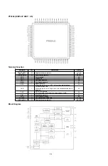
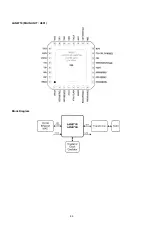
PT6302 (DISPLAY UNIT : U5)
Terminal Function
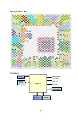
Block Diagram
Pin Name
I/O
Description
Pin No.
SG5 to SG35
SG4 to SG1
O
Segment driver output pin
1 ~ 31
64 ~ 61
7
4
~
2
3
n
i
p
t
u
p
t
u
o
r
e
v
ir
d
d
ir
G
O
6
1
R
G
o
t
1
R
G
8
4
y
l
p
p
u
s
r
e
w
o
P
-
E
E
V
9
4
n
i
p
d
n
u
o
r
G
-
S
S
V
0
5
n
i
p
t
u
p
n
i
r
o
t
a
ll
i
c
s
O
I
I
C
S
O
1
5
n
i
p
t
u
p
t
u
o
r
o
t
a
ll
i
c
s
O
O
O
C
S
O
RSTB
I
Reset input pin
When this pin is set to "LOW", all functions are initialized.
52
CSB
I
Chip select input pin
When this pin is set to "High" Level, the serial data transfer is
disabled.
53
CLKB
I
Shift clock input pin
The serial data is shifted at the rising edge of CLKB.
54
5
5
n
i
p
t
u
p
n
i
a
t
a
d
l
a
ir
e
S
I
N
I
D
6
5
y
l
p
p
u
s
r
e
w
o
p
e
v
it
i
s
o
P
-
D
D
V
8
5
~
7
5
n
i
p
t
u
p
t
u
o
e
s
o
p
r
u
p
l
a
r
e
n
e
G
O
2
P
o
t
1
P
0
6
~
9
5
n
i
p
t
u
p
t
u
o
r
e
v
ir
d
t
n
e
m
g
e
S
O
1
D
A
o
t
2
D
A
Summary of Contents for DBP-2012UDCI
Page 40: ...40 Personal notes ...
Page 76: ...Personal notes Personal notes 76 ...
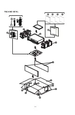
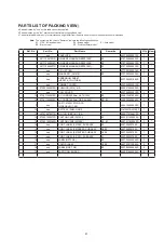
Page 80: ...80 PACKING VIEWs 7 8 8 14 15 16 17 19 18 17 16 19 9 13 12 11 10 z 1 3 4 5 6 ...
Page 86: ...86 LAN8710 MAIN UNIT U901 Block Diagram ...
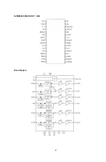
Page 87: ...87 NJM2566AV MAIN UNIT U20 Block Diagram ...
Page 91: ...91 2 FL DISPLAY FL TUBE 15 BT 114GNK Display UNIT U3 ...
Page 92: ...92 Personal notes ...


