


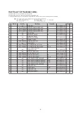


82
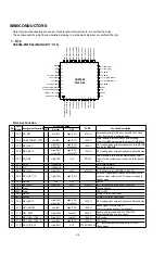
SEMICONDUCTORS
Only major semiconductors are shown. Genaral semiconductors etc. are omitted from list.
The semiconductors which have a detailed drawing in a schematic diagram are omitted from list.
1. IC's
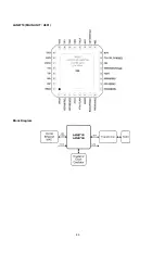
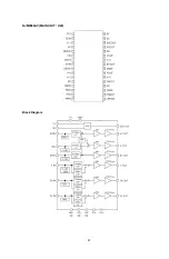
CS8966-PQFP44 (MAIN UNIT : U16)
Terminal Function
Pin
Port
Name
Assignment Function
I/O Port De
fi
nition
PU/PD
Function Description
I/O
Normal
OFF
1
P3.7 DC_DET
I
Low(0V)
High(3.3V)
47k PD
Detection signal is for DC short circuit(3.3V;+5V and
+12V). It only work in power-on mode.
2
P3.6 HDMI_POWER_CTRL O
Low(0V)
High(3.3V)
10k PU
Power enable is for the HDMI 5V power supply.
High is for HDMI work normal.And low is for HDMI off.
3
P3.5 MCU_SET1
I
High(3.3V)
or Low(0V)
High(3.3V)
or Low(0V)
10k PU
MCU setting pin by externail resistance.1 is for DENON
and 0 is for MARANZ
4
P2.3 MCU_SET2
I
High(3.3V)
or Low(0V)
High(3.3V)
or Low(0V)
10k PU
MCU setting pin by externail resistance. Default is high.
5
P2.2 PS_ON#
O
High(3.3V)
Hi-Z
PD 47k
Power enable is to control the system power on/off.
High is for the system power on and low is for standby
mode.
6
P2.1 XOUT
O
11.059MHz
-
-
For crystal oscillator
7
P2.0 XIN
I
11.059MHz
-
-
For crystal oscillator
8
P4.1 MCU_SDA
I/O
High(3.3V)
Hi-Z
4.7K PU
I2C DATA signal is for EEPRM IC (24C02).
9
P4.0 MCU_CEC_IN
I
High(3.3V)
High(3.3V)
HDMI CEC signal input.It wakes-up to the system to
power on when receive the CEC power command in
standby mode.
10
P3.4 Not use
-
Hi-Z
Hi-Z
-
Not use
11
P4.3 MCU_SCL
O
High(3.3V)
Hi-Z
4.7K PU
I2C Clock signal is for EEPRM IC (24C02).
12
VSS Power
-
-
-
-
Ground Voltage
13 RXVDD Power
-
-
-
-
VDD for RTC
14
RXIN Not use
I
-
-
-
Crystal IN for RTC oscillator
15 RXOUT Not use
O
-
-
-
Crystal OUT for RTC oscillator
16
P4.2 MCU_SET3
I
High(3.3V)
or Low(0V)
High(3.3V)
or Low(0V)
10k PU
MCU setting pin by externail resistance. Default is high.
17
P1.7 MCU_AMUTE
O
Low(0V)
High(3.3V)
10k PU
Muting signal for audio output.
High is for muting and Low is muting off.
18
P1.6 DAC_RST#
O
High(3.3V)
Low(0V)
10k PD
Reset singal is for audio DAC IC PCM1795.
High is normal and Low is for reset.
19
P1.5 MCU_LED_CTRL_A
O
High(3.3V)
Low(0V)
10k PD
LED control
20
P1.4 MCU_LED_CTRL_B
O
Low(0V)
High(3.3V)
10k PD
LED control
21
P1.3 MCU_IIC_SCL
I
High(3.3V)
Hi-Z
4.7K PU SW3.3V
I2C Clock signal that comunicate with MT8530.
(Slave mode).
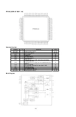
PG
AV
MID
/
P3.
7
/ SPI
CLK
RXVDD
P2.4 / T2EX / CMPD
34
1
P1.4 / SWC2
P1.5 / SWC3
P3.0 / CEX2 / SWA1 / CMPA
P3.1 / CEX3 / SWA2 / CMPA
P3.4
/ SS
P1.2 / SDA / SWC0
P2.5 / T2 / CMPC
PGAOUT1 / P3.2 / CEX4
PGAIN1 / P3.3 / CEX5
P4.2 / SWB3
P2.2
/
TX
D
1
P2.6 / CMPB
P2.7 / CMPA / SWA0
RSTN
P1.1
/ AD
D4
/ CEX
1
P1.0
/ AD
D3
/ CEX
0
P0.7
/ RX
D0
/ ADD
2
P0.6
/ TXD
0
/ A
DD1
P0.0
/
PI
NT1.
0
/ A
D
A
1
P2
.3
/
R
X
D
1
P2
.1
/ XOUT
P2
.0
/
XIN
P1.7 / T0 / SWB0 / PINT0.1
P1.6 / T1 / SWB1 / PINT0.0
P1.3 / SCL / SWC1
PG
A
O
U
T
2
/ P
3.
5
/
M
O
S
I
P4
.3
/
S
C
L
2
P4.
1
/ S
D
A
2
VSS
PG
AI
N2
/ P3.6
/
M
ISO
P0.5
/
PI
NT1.
5
/ A
D
C
2
P0.4
/
PI
NT1.
4
/ A
D
C
1
P0.3
/
PI
NT1.
3
/ A
DB
2
P0.1
/
PI
NT1.
1
/ A
D
A
2
P4
.0
/
C
E
C
VDD
VDD25
P0.2
/
PI
NT1.
2
/ A
D
B
1
RXIN
RXOUT
VSS
44
35
36
37
38
39
40
41
42
43
23
24
25
26
27
28
29
30
31
32
33
2
3
4
5
6
7
8
9
10
11
22
21
20
19
18
17
16
15
14
13
12
CS8966F
PQFP-44
Summary of Contents for DBP-2012UDCI
Page 40: ...40 Personal notes ...
Page 76: ...Personal notes Personal notes 76 ...
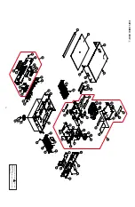
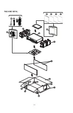
Page 80: ...80 PACKING VIEWs 7 8 8 14 15 16 17 19 18 17 16 19 9 13 12 11 10 z 1 3 4 5 6 ...
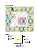
Page 86: ...86 LAN8710 MAIN UNIT U901 Block Diagram ...
Page 87: ...87 NJM2566AV MAIN UNIT U20 Block Diagram ...
Page 91: ...91 2 FL DISPLAY FL TUBE 15 BT 114GNK Display UNIT U3 ...
Page 92: ...92 Personal notes ...