background image

9

Basic version

Advanced version

Information

ENGLISH

Simple version

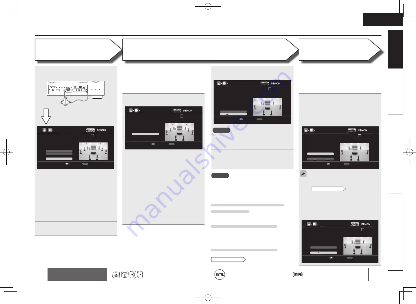
Set up speakers (Audyssey® Auto Setup)

STEP 1

 Preparation

Remote control operation 

buttons

Move the cursor 
(Up/Down/Left/Right)

Confi rm the setting

Return to previous menu

STEP 2

 Detection & Measurement


(Main listening position)

STEP 3

Measurement


(2nd – 8th listening position)

7

The detected speakers are displayed.

AUDYSSEY AUTO SETUP

1 2 3 4 5 6

RETURN

Next    Measurement

Retry

STEP2 Speaker Detection Check

Front

Center

Subwoofer

Surround

Surround Back

Front Height

Front Wide

Yes

Yes

1spkr

Yes

2spkrs

No

No

Proceed to STEP 3 after checking speaker connection result

Enter

Cancel

NOTE

If  a  connected  speaker  is  not  displayed,  the 
speaker  may  not  be  connected  correctly.  Check 
the speaker connection. 

8

Use 

ui

 to select “Next 


Measurement” and then press 

ENTER

.

• In  STEP  3,  you  will  perform  measurements  at 

multiple  positions  (two  to  eight  positions)  other 
than the main listening position.

• You  can  achieve  a  more  effective  correction  of 

distortion within the listening area by performing 
measurements at multiple positions.

9

Move the setup microphone to 

position 2, use 

ui

 to select 

“Measure”, and then press 

ENTER

The  measurement  of  the  second  position 
starts. Measurements can be made in up to 
eight positions.

AUDYSSEY AUTO SETUP

1 2 3 4 5 6

RETURN

Next    Calculation

Measure

STEP3 Measurement(2nd-8th)

Please place the microphone at ear

height at 2nd Iistening position.

Start measurement. Output large test tone during measuring

Enter

Cancel

If you want to omit measurements from the next 
position onward, select “Next 

 Calculation”.

(Go to 

STEP4

 Calculation

)

10

Repeat step 9, measuring positions 3 

to 8.

When measurement of position 8 is 
completed, a “Measurements fi nished.” 
message is displayed.

AUDYSSEY AUTO SETUP

1 2 3 4 5 6

RETURN

Next    Calculation

Proceed to STEP4 (Calculation)

Enter

Cancel

Retry

STEP3 Measurement(2nd-8th)

Measurements finished.

NOTE

If “Caution” is displayed:

Go  to  “Error  messages”  (

v

page  11),  check 

any  related  items,  and  perform  the  necessary 
procedures.

When performing Audyssey Auto 

Setup over again 

Press 

ui

 to select “Retry”, and then press 

ENTER

When measuring has stopped

Press 

RETURN

, to the “Cancel auto setup?” prompt 

is displayed.
Press 

o

 to select “Yes”, then press 

ENTER

.

Setting up the speakers again

Repeat the operation from step 4 of 

STEP1

 Preparation

.

• In STEP 2, you will perform measurements at the 

main listening position.

• This  step  automatically  checks  the  speaker 

confi guration and speaker size, and calculates the 
channel level, distance, and crossover frequency. 
It also corrects distortion in the listening area.

6

Select  “Measure”  and  then  press 

ENTER

.

AUDYSSEY AUTO SETUP

1 2 3 4 5 6

RETURN

Measure

STEP2 Detection & Measurement (main)

Please place the microphone at ear

height at main Iistening position.

Start measurement. Output large test tone during measuring

Enter

Cancel

Measure the subwoofer level

• To stop measuring, select “Cancel” and then 

press 

ENTER

.

• When  “Subwoofer”  is  set  to  “Skip”  with 

“Channel  Select”,  this  measurement  is  not 
taken,  and  the  process  proceeds  to  “

w


Measure each speaker”.

Measure each speaker

• Once  the  measurements  in  step 

q

  are 

complete, the measurements in step 

w

 start 

automatically.

• The  measuring  channel  changes  depending 

on  the  setting  of  “Set  up  “Amp  Assign”” 
(

v

page 59) and “Set up “Channel Select”” 

(

v

page 60).

• Measurement requires several minutes.

4

Connect the setup microphone to the 

SETUP MIC jack of this unit.

AUDYSSEY AUTO SETUP

1 2 3 4 5 6

Amp Assign

RETURN

Auto Setup Start

Channel Select

STEP1 Preparation

Connect the speakers and place them according

to the 

recommendations in the manual,

Set the following items

If necessary.

Start Auto Setup

Enter

Cancel

When the setup microphone is 
connected, the following screen is 
displayed.

This  screen  provides  the  method  for  setting 
up  7.1-channel  playback  using  surround  back 
speakers. For the method of setting up speakers 
other than the 7.1-channel system, select “Amp 
Assign”  and  perform  step  3  and  7  of  “Set  up 
“Amp Assign”” (

v

page 59).

If unused channels are set with “Channel Select”, 
measuring  time  can  be  shortened.  Also,  set 
“Channel  Select”  to  measure  two  subwoofers.
For  setting,  perform  steps  9  to  14  of  “Set  up 
“Channel Select”” (

v

page 60).

5

Use 

ui

 to select “Auto Setup Start” 

and then press 

ENTER

.

1.AVR4311E2_ENG_6th_0810.indd   9

2010/08/12   10:11:36

Summary of Contents for AVR-4311

Page 1: ...sique Versión básica v 14 Advanced version Version avancée Versión avanzada v 49 Information Part names and functions vpage 116 v 115 Informations Nomenclature et fonctions vpage 116 Información Nombres y funciones de las piezas vpágina 116 v Book 1 English Français Español Book 2 Deutsch Italiano Nederlands Svenska 1 AVR4311E2_ENG_6th_0810 indd 1 2010 08 12 10 11 30 ...

Page 2: ...tructions 5 Do not use this apparatus near water 6 Clean only with dry cloth 7 Do not block any ventilation openings Install in accordance with the manufacturer s instructions 8 Do not install near any heat sources such as radiators heat registers stoves or other apparatus including amplifiers that produce heat 9 Protect the power cord from being walked on or pinched particularly at plugs convenie...

Page 3: ... unità per un lungo periodo di tempo Non coprite i fori di ventilazione Non inserite corpi estranei all interno dell unità Assicuratevi che l unità non entri in contatto con insetticidi benzolo o solventi Non smontate né modificate l unità in alcun modo Le aperture di ventilazione non devono essere ostruite coprendole con oggetti quali giornali tovaglie tende e così via Non posizionate sull unità ...

Page 4: ...s entspricht EN60065 EN55013 EN55020 EN61000 3 2 und EN61000 3 3 Following the provisions of low voltage directive 2006 95 EC and EMC directive 2004 108 EC the EC regulation 1275 2008 and its frame work directive 2009 125 EC for energy related products ErP DECLARATION DE CONFORMITE Nous déclarons sous notre seule responsabilité que l appareil auquel se réfère cette déclaration est conforme aux sta...

Page 5: ...dio stations 33 Playing a network audio 36 Playing a USB memory device 44 Selecting a listening mode Surround Mode 46 Standard playback 46 DENON original surround playback 48 Stereo playback 48 Direct playback 48 Pure direct playback 48 Advanced version 49 Speaker installation connection Advanced connection 50 Install 50 Connect 52 Set up speakers 59 Playback Advanced operation 61 Convenient funct...

Page 6: ...eater sense of space is produced in the sound images High definition audio support The unit is equipped with a decoder which supports high quality digital audio format for Blu ray Disc players such as Dolby TrueHD DTS HD Master Audio etc Audyssey MultEQ XT 32 Audyssey MultEQ corrects both time and frequency response problems in the listening area so that every listener can enjoy music and movie wi...

Page 7: ...nstructions when using a chemical cleaner Benzene paint thinner or other organic solvents as well as insecticide may cause material changes and discoloration if brought into contact with the unit and should therefore not be used Features Easy to use Graphical User Interface This unit is equipped with an easy to see Graphical User Interface that uses menu displays and levels The use of level displa...

Page 8: ...operation of the connected devices refer to the user manuals for each device Play back disc vpage 13 Enjoy Blu ray Disc in surround sound 5 Set up speakers vpage 7 Use the setup microphone DM A409 included with the product for automatic setup 4 Finish STEP 6 Store STEP 5 Check STEP 4 Calculation STEP 3 Measurement 2nd 8th listening position STEP 2 Detection Measurement Main listening position STEP...

Page 9: ... where one speaker has an impedance of 4 to 16 Ω When using a speaker with impedance of 4 Ω or 6 Ω make sure to set the Speaker Impedance in the menu vpage 94 to 6 Ω ohms or 4 Ω ohms Install 1 2 3 4 5 This unit can perform 2 0 to 11 2 channel surround playback This page provides the speaker installation procedure for the 7 1 channel playback using surround back speakers as an example FL FR C SBL S...

Page 10: ...s not support the ARC function vpage 16 make the audio connection referring to Connecting a TV vpage 18 TV sound can be played on this unit NOTE Do not plug in the power cord until all connections have been completed Do not bundle power cords together with connection cables Doing so can result in humming or noise Connect FL FR C SL SR SW SBL SBR Speaker cables sold separately Audio cable sold sepa...

Page 11: ...as Radio Frequency Interference RFI may cause measurement disruptions even if the cell phone is not in use Do not unplug the setup microphone from the main unit until Audyssey Auto Setup is completed Do not stand between the speakers and setup microphone or allow obstacles in the path while the measurements are being made This will cause inaccurate readings Loud test sounds may be played during Au...

Page 12: ...bwoofer calibration you must select Measure 2 spkrs in Set up Channel Select vpage 60 The Simple version section provides the speaker installation connection and setup methods for the 7 1 channel system with surround back speakers For the installing connecting and setup methods of speakers other than the 7 1 channel system with surround back speakers see page 50 Set up speakers Audyssey Auto Setup...

Page 13: ...ey Auto Setup over again Press ui to select Retry and then press ENTER When measuring has stopped Press RETURN to the Cancel auto setup prompt is displayed Press o to select Yes then press ENTER Setting up the speakers again Repeat the operation from step 4 of STEP1 Preparation In STEP 2 you will perform measurements at the main listening position This step automatically checks the speaker configu...

Page 14: ...ress o then select Yes All the measured Audyssey Auto Setup data will be erased NOTE During saving of measurement results be sure not to turn off the power Remote control operation buttons Move the cursor Up Down Left Right Confirm the setting Return to previous menu NOTE If the result differs from the actual connection status or if Caution is displayed see Error messages vpage11 ThencarryoutAudys...

Page 15: ...er or subwoofer sound is too low for accurate measurements to be made Either turn off any device generating noise or move it away Perform again when the surroundings are quieter Check the speaker installation and the direction in which the speakers are facing Adjust the subwoofer s volume AUDYSSEY AUTO SETUP 1 2 3 4 5 6 RETURN Front R None Check cause of problem Cancel Caution Retry The displayed ...

Page 16: ...he measured level appears on the level indicator after about 3 to 5 seconds AUDYSSEY AUTO SETUP 1 2 3 4 5 6 RETURN Next dB SW Test Start Subwoofer Level Matching Please place the microphone at ear height at main listening position then push ENTER Start measurement Output test tone from subwoofer Enter Cancel AUDYSSEY AUTO SETUP 1 2 3 4 5 6 79 1dB Stop Subwoofer Level Matching Please adjust the lev...

Page 17: ...listening mode according to the playback contents cinema music etc or according to your liking vpage 46 Selecting a listening mode Surround Mode When power is switched to standby Press POWER OFF GPower indicator status in standby modeH Normal standby Off When HDMI Control Control is set to ON Red When Network Standby is set to ON Red You can also switch the power to standby by pressing ON STANDBY ...

Page 18: ...9 vpage 29 Set top box Satellite tuner or cable TV vpage 17 19 Digital video recorder vpage 17 20 Game console vpage 17 Digital camcorder vpage 21 Control dock for iPod vpage 21 vpage 30 Audio Playback Connection iPod vpage 22 vpage 32 USB memory device vpage 22 vpage 44 Radio vpage 23 vpage 33 Record player vpage 23 CD player vpage 24 vpage 30 Network Playback Connection Network vpage 26 vpage 36...

Page 19: ...ZONEH HDMI connector Component video connectors S Video connector Video connector Monitor HDMI connector Component video connectors Component video connectors Component video connectors S Video connector Video connector HDMI connector Video connector HDMI connector Video connector Video device This unit Output Input IN Output MONITOR OUT Input when 480i 576i signals are input Connections GFlow of ...

Page 20: ...ble or High Speed HDMI cable with Ethernet When the ARC function is used connect a device with a Standard HDMI cable with Ethernet or High Speed HDMI cable with Ethernet for HDMI 1 4a HDMI control function vpage 61 This function allows you to operate external devices from the receiver and operate the receiver from external devices NOTE The HDMI control function may not work depending on the device...

Page 21: ...ble inputs Connecting to a device equipped with a DVI D connector When an HDMI DVI conversion cable sold separately is used the HDMI video signals are converted to DVI signals allowing connection to a device equipped with a DVI D connector NOTE No sound is output when connected to a device equipped with a DVI D connector Make separate audio connections Signals cannot be output to DVI D devices tha...

Page 22: ...N VIDEO AUDIO OPTICAL OUT VIDEO COMPONENT VIDEO Y PB PR IN TV Set this to change the digital input connector or component video input connector to which the input source is assigned Input Assign vpage 77 in Set as Necessary Connecting a Blu ray Disc player You can enjoy video and audio from a Blu ray Disc Select the connector to use and connect the device For instructions on HDMI connections see C...

Page 23: ...t connector to which the input source is assigned Input Assign vpage 77 in Set as Necessary Connecting a set top box Satellite tuner cable TV You can watch satellite or cable TV Select the connector to use and connect the device For instructions on HDMI connections see Connecting an HDMI compatible device vpage 16 Cables used for connections Video cable sold separately Video cable Yellow Component...

Page 24: ...onent video cable Green Blue Red S Video cable Audio cable sold separately Audio cable White Red R L R L Optical cable R L R L R L R L R L R L OUT IN AUDIO VIDEO VIDEO OUT IN OPTICAL OPTICAL IN AUDIO AUDIO OUT VIDEO OUT S VIDEO VIDEO COMPONENT VIDEO Y PB PR OUT AUDIO Digital video recorder NOTE To record video signals through this unit use the video cable for connection between this unit and the p...

Page 25: ...e other source is input the video conversion function might not operate In this case use the monitor output of the same connector as the input Connecting a control dock for iPod Connect a control dock for iPod to the unit to enjoy video and music stored on an iPod For a control dock for iPod use ASD 1R and ASD 11R made by DENON sold separately For instructions on the control dock for iPod settings...

Page 26: ...to supply power use the AC adapter NOTE You cannot use the USB ports on the front panel and rear panel simultaneously Select and connect the USB port to use USB memory devices will not work via a USB hub Do not use an extension cable when connecting a USB memory device This may cause radio interference with other devices This unit does not support playback on an iPad Do not connect an iPad to the ...

Page 27: ...tenna is used do not disconnect the AM loop antenna Make sure the AM loop antenna lead terminals do not touch metal parts of the panel If the signal has noise interference connect the ground terminal GND to reduce noise If you are unable to receive a good broadcast signal we recommend installing an outdoor antenna For details inquire at the retail store where you purchased the unit Connecting a re...

Page 28: ...ions Audio cable sold separately DENON LINK cable DENON LINK AUDIO Blu ray Disc player DVD player When connecting by use of DENON LINK set Digital to D LINK Input Assign vpage 77 in Set as Necessary Component with Multi channel Output connectors You can connect this unit to an external device fitted with multi channel sound audio output jacks to enjoy music and video The video signal can be connec...

Page 29: ...L R L R L R L SUB WOOFER 1 SUB WOOFER 2 CENTER SURROUND BACK R L SURROUND R L FRONT HEIGHT R L FRONT WIDE R L FRONT R L AUDIO AUDIO Power amplifier Subwoofer When using just one surround back speaker connect it to the left channel L terminal Use the volume control on the subwoofer to control subwoofer volume If the subwoofer volume sounds low use the volume control provided on the subwoofer to adj...

Page 30: ...mended Use only shielded STP or ScTP LAN cable which is available at retailer Some flat type Ethernet cables are easily affected by noise We recommend using a normal type cable If you have an Internet provider contract for a line on which network settings are made manually make the settings at Network Setup vpage 97 With this unit it is possible to use the DHCP and Auto IP functions to make the ne...

Page 31: ...n the power of this unit w Turn off the power of this unit from the external controller e Check that the unit is in the standby mode TRIGGER OUT jacks When a device with TRIGGER IN jack is connected the connected device s power on standby can be controlled through linked operation to this unit The TRIGGER OUT jack outputs a maximum 12 V 150 mA electrical signal 12 V 150 mA trigger compatible devic...

Page 32: ...RCE SELECT Display the SOURCE SELECT menu SOURCE SELECT Source SAT CBL Recent Player Video Network Tuner Enter Move The currently selected input source is highlighted q w e q Input Source The name of the highlighted input source is displayed w Recently used sources The recently used input sources up to five are displayed e Icons for the input sources in the different categories are displayed w Use...

Page 33: ...vpage 80 The default setting of Input Mode is Auto 7 Play the component connected to this unit Make the necessary settings on the player language setting subtitles setting etc beforehand NOTE Set the Blu ray disc player s DENON LINK setting to 4th For instructions on operation refer to the Blu ray disc player s manual The low jitter transmission function does not work except during Blu ray disc pl...

Page 34: ...is displayed on a TV screen depending on the connected control dock for iPod Music Playlists Artists Albums Songs Genres Composers 1 6 iPod Music Videos 1 2 When using an ASD 1R When using an ASD 11R In Browse mode the iPod display is as shown at right NOTE If the connections screen is not displayed the iPod may not be properly connected Reconnect it OK to disconnect 4 Press SEARCH and hold it dow...

Page 35: ...s and videos on an iPod in the Remote mode This unit can play back on a TV screen photos and data stored on an iPod equipped with a slide show or video function 1 Press and hold SEARCH to set the Remote mode Remote iPod or Dock Remote is displayed on the display of this unit 2 Watching the iPod s screen use ui to select Photos or Videos Depending on the iPod model it may be necessary to operate th...

Page 36: ...select the file to be played 7 Press ENTER p or 1 Playback starts You can specify the duration of the on screen display to be displayed default 30 sec at menu iPod vpage 100 Press uio p to return to the original screen To play back compressed audio with extended bass or treble reproduction we recommend playback in RESTORER mode vpage 88 The default setting is Mode3 In Browse mode press STATUS duri...

Page 37: ... in easily Up to 56 stations can be preset Stations can be preset automatically at Auto Preset vpage 77 If Auto Preset is performed after performing Manual Preset the Manual Preset settings will be overwritten 1 Tune in the broadcast station you want to preset 2 Press MEMORY 3 Press SHIFT to select the block A to G in which the channel 1 to 8 per a block is to be preset then press CH CH or 1 8 to ...

Page 38: ...lly If no RDS stations are found with the above operation all the reception bands are searched When a broadcast station is found that station s name appears on the display If no RDS station is found when all the frequencies have been searched NO RDS is displayed If you press CH or CH within 5 seconds after the broadcast station name is shown on the display you can search for a different station PT...

Page 39: ... all the reception bands are searched The station name is displayed on the display after searching stops If no other TP station is found when all the frequencies have been searched NO PROGRAMME is displayed If you press CH or CH within 5 seconds after the broadcast station name is shown on the display you can search for a different station RT Radio Text RT allows RDS stations to send text messages...

Page 40: ... in the orientation in which they are stored in the folder GCompatible formatsH Internet radio Media server z1 WMA Windows Media Audio P P MP3 MPEG 1 Audio Layer 3 P P WAV P MPEG 4 AAC Pz2 FLAC Free Lossless Audio Codec P JPEG P A server or server software compatible with distribution in the corresponding formats is required to play music files via a network z1 Media server This unit is compatible...

Page 41: ...her the sound quality but depending on the communication lines and server traffic the music or audio signals being streamed may be interrupted Inversely lower bit rates mean a lower sound quality but less tendency for the sound to be interrupted Server Full or Connection Down is displayed if the station is busy or not broadcasting On this unit folder and file names can be displayed as titles Any c...

Page 42: ...SOURCE SELECT to display the SOURCE SELECT menu then select vpage 28 2 Press ui to select the Internet radio station you want to clear then press MEMORY 3 Press o to select Remove The selected Internet radio station is cleared To cancel the operation without clearing the station press p n Internet radio operation Operation buttons Function CH Preset channel selection MENU Amp menu uio p Cursor ope...

Page 43: ...etting is Mode3 You can specify the duration of the on screen display to be displayed default 30 sec at menu NET USB vpage 100 Press uio p to return to the original screen Use STATUS to switch between displaying the title name artist name or album name n n Playing files that have been preset or registered in your favorites Files can be preset registered in your favorites and played using the same ...

Page 44: ...Displays a list of shared photographs PhotoSets Displays the folder photograph album list Contacts Displays a Username registered for Flickr Contact by a specified user Remove this Contact Deletes a user from Flickr Contact 7Press ui to select the file and then press ENTER or p The selected file is displayed n Viewing all photographs on Flickr 1 Prepare for playback q Check the network environment...

Page 45: ...ount OK Enter Username Username Password RETURN Cancel For character input see page 74 4After inputting the Username and Password select OK then press ENTER If the Username and Password match the top menu for Napster is displayed NOTE The password should be no longer than 99 characters Press RETURN to cancel the input When Cancel input is displayed select Yes then press ENTER n n Searching from Na...

Page 46: ...wer on standby Default SONY TV INPUT Switch TV input Default SONY Repeat playback vpage 81 Repeat Random playback vpage 81 Random z When the menu screen is displayed press SEARCH twice then press o previous page or p next page To cancel press ui or SEARCH How to listen to Last fm on this unit Last fm radio is not available in all countries Please check www last fm hardware for more information You...

Page 47: ...this track If you ban a track we won t play it again You can undo this on the Last fm website Scrobbling Scrobbling sends the tracks you played to your Last fm account You can see charts of the music you ve been listening to get recommendations for new music and events in your area and share your listening tastes with your friends You can turn this service on or off using this option The more you ...

Page 48: ...mbedded by using MP3 ID3 Tag Ver 2 3 or 2 4 This unit is compatible with WMA META tags WAV format Quantization bit rate 16 bits FLAC format Quantization bit rate 16 or 24 bits z2 Copyright protected files can be played on certain portable players compatible with MTP z3 Only files that are not protected by copyright can be played on this unit Content downloaded from pay sites on the Internet are co...

Page 49: ... draw power from an AC adapter we recommend using the AC adapter It is not possible to connect and use a computer via the USB port of this unit using a USB cable Playing a USB memory device n n USB operation Operation buttons Function CH Preset channel selection MENU Amp menu uio p Cursor operation Auto search cue ui ENTER Press and release Enter Pause ENTER Press and hold Stop SEARCH Page searchz...

Page 50: ... 46 For 2 channel signal input Surround channel signals are created and played with surround playback For multichannel signal input The surround signal recorded in source is played as surround playback The sound is played according to the settings of the speaker size in Speaker Config vpage 91 Surround back channel or front height channel signals that are not recorded in source can be created 2 ch...

Page 51: ...OLBY DIGITAL Plus EX DOLBY D EX DOLBY DIGITAL Plus PLgx CINEMA DOLBY D PL x C DOLBY DIGITAL Plus PLgx MUSIC DOLBY D PL x M DOLBY DIGITAL Plus PLgz HEIGHT DOLBY D PL z DOLBY TrueHD DOLBY TrueHD DOLBY TrueHD DOLBY TrueHD EX DOLBY HD EX DOLBY TrueHD PLgx CINEMA DOLBY HD PL x C DOLBY TrueHD PLgx MUSIC DOLBY HD PL x M DOLBY TrueHD PLgz HEIGHT DOLBY HD PL z DTS 5 1ch DTS ES Discrete 6 1 DTS ES Matrix 6 ...

Page 52: ...ont left and right speakers and subwoofer If multichannel signals are input they are mixed down to 2 channel audio and are played 1 Playing the source vpage 29 45 2 Press D ST to select STEREO Stereo playback begins If DIRECT STEREO on the main unit is pressed the same function as with the remote control unit can be obtained Direct playback Sound recorded in source is played as is Surround back si...

Page 53: ... F Playback Advanced operation vpage 61 F Playback in ZONE2 ZONE3 Separate room vpage 68 F How to make detailed settings vpage 71 F Operating the connected devices by remote control unit vpage 104 Advanced version Here we explain functions and operations that let you make better use of this unit 1 AVR4311E2_ENG_6th_0810 indd 49 2010 08 12 10 11 54 ...

Page 54: ...ompatible with Audyssey DSX vpage 128 and Dolby Pro Logic gz vpage 129 which offers an even wider and deeper surround sensation When using Audyssey DSX install front wide speakers or front height speakers When using Dolby Pro Logic gz install front height speakers Install the surround back speakers in a position 60 to 90 cm higher than ear level z1 z2 45 Surround speaker 60 90 cm GViewed from the ...

Page 55: ...ion z1 22 30 z2 120 When Front A B speakers installed FR A FR B SW FL B FL A Listening position FL Front speaker L SBL Surround back speaker L FR Front speaker R SBR Surround back speaker R C Center speaker FHL Front height speaker L SW Subwoofer FHR Front height speaker R SL Surround speaker L FWL Front wide speaker L SR Surround speaker R FWR Front wide speaker R SB Surround back speaker 1 AVR43...

Page 56: ...wide speakers before you start playback the audio is played back by automatically switching the speakers in accordance with the surround mode or input signals To set the speakers for automatic switching select Amp Assign and set Assign Mode to NORMAL using steps 3 and 4 of Set up Amp Assign vpage 59 n n For connecting two subwoofers Two subwoofers can be connected to this unit To use two subwoofer...

Page 57: ... depending on the speaker s specifications or playback source such as front speakers A for multichannel playback and front speakers B for 2 channel playback vpage 94 Front Speaker Setup 6 1 channel Surround back speaker connection If using only one surround back speaker with a 6 1 channel connection connect to the L side of the SURR BACK AMP ASSIGN terminal For speaker settings in this case see Wh...

Page 58: ...k with higher quality sound To use the bi amp connection for the front speakers select Amp Assign and set Assign Mode to Bi AMP using steps 3 and 4 of Set up Amp Assign vpage 59 FL FR SW w q w q R L z You can also connect the front speakers for bi amp connection to SURR BACK AMP ASSIGN or F HEIGHT AMPASSIGNspeakerterminalsusingthe AmpAssign AssignSp settings vpage91 To perform multichannel playbac...

Page 59: ...tion You can connect the other front speakers for 2 channel playback using the DIRECT mode or STEREO mode The speakers used exclusively for multichannel playback and the speakers used exclusively for 2 channel playback are automatically switched for playback in accordance with the surround mode To set the speakers for automatic switching during playback select Amp Assign and set Assign Mode to 2CH...

Page 60: ...lly switched for playback in accordance with the surround mode To set the speakers for automatic switching during playback via the bi amp connection select Amp Assign and set Assign Mode to 2CH Bi AMP using steps 3 and 4 of Set up Amp Assign vpage 59 z zBi Amp connection FR FR FL FL C SBL SBR SL SR SW Multi channel playback Surround mode 2 channel playback Direct Stereo mode Switching For speaker ...

Page 61: ...l power amplifier for 2 channel Connect the external amplifier to the PRE OUT connector To perform 11 2 channel playback select Amp Assign and set Assign Mode to 11CH using steps 3 and 4 of Set up Amp Assign vpage 59 z You can also change the PRE OUT connector for connecting the power amplifier to the Front channel using the Amp Assign Ext Amp settings vpage91 Changethesettinginaccordance with you...

Page 62: ...mp Assign and set Assign Mode to PRE AMP using steps 3 and 4 of Set up Amp Assign vpage 59 When the PRE AMP mode is used the MAIN ZONE audio is not output from the speaker terminals of this unit To use the speakers for multizone ZONE2 ZONE3 in the PRE AMP mode set Amp Assign Assign Sp to ZONE2 3 vpage 91 This setting will output the ZONE2 audio from the surround back speaker terminals and ZONE3 au...

Page 63: ...he number of subwoofers or surround back speakers vpage 60 Set up Channel Select 3 Set up Amp Assign Use ui to select Amp Assign and then press ENTER RETURN 7 2 ch 9 2 ch Return Assign Mode NORMAL ZONE2 ZONE3 AUDYSSEY AUTO SETUP AUDYSSEY AUTO SETUP 1 2 3 4 5 6 Amp Assign RETURN Auto Setup Start Channel Select STEP1 Preparation Connect the speakers and place them according to the recommendations in...

Page 64: ...Cancel Surround Back Measure 2 spkrs Front Height Measure Front Wide Measure RETURN AUDYSSEY AUTO SETUP 1 2 3 4 5 6 Amp Assign RETURN Auto Setup Start Channel Select STEP1 Preparation Connect the speakers and place them according to the recommendations in the manual Set the following items If necessary Enable skip of measuring unused channels to reduce time Enter Cancel 10Use ui to select a channe...

Page 65: ...standby even if the connected device is in the standby mode When connection changes are implemented such as adding connections to HDMI devices linked operations may be initialized In this case you will need to reconfigure the settings When HDMI Control Control is set to ON it is not possible to assign an HDMI connector to TV at Input Assign vpage 78 1 Set the HDMI output connector corresponding wi...

Page 66: ... 0 0dB 0 0dB ON 4 Use ui to select the speaker The speaker that can be set switches each time one of the buttons is pressed 5 Use o p to adjust the volume You can directly turn OFF the subwoofer outputs during 2 channel playback in DIRECT or STEREO mode Select Subwoofer and use o p to select ON or OFF CHANNEL LEVEL Front L Front R 8 0dB 12 0dB Subwoofer OFF When a headphone jack is inserted the he...

Page 67: ...ord the audio or video from a different program source while listening to the currently played track 1 Press ZONE2 3 REC SELECT ZONE2 SOURCE is shown on the display 2 Turn SOURCE SELECT until RECOUT SOURCE is displayed The indicator illuminates ZONE2 SOURCE ZONE2 TUNER ZONE2 NET USB RECOUT NET USB RECOUT DOCK RECOUT SOURCE 3 Turn SOURCE SELECT to choose the input source to be recorded For operatin...

Page 68: ...splayed 3 Press o p to select Yes or No then press ENTER Yes The power of the attendees is turned off and the party mode is canceled No The party mode is canceled without turning off the power of the attendees n n Participating in the party mode as an attendee When the organizer starts the party mode up to four attendees are selected automatically No operation is required When a device becomes an ...

Page 69: ...ct a player e Start playback r Operate Wireless LAN compatible router Media controller 1 Select the content you want to play from among the media controller 2 From the media controller select this unit from among the products on the network Playback of the content selected in step 1 begins When selecting this unit from the media controller the name of this unit is displayed at Friendly Name vpage ...

Page 70: ...vGExample 3H t Click when you operate a small screen such as a PDA screen etc vGExample 4H 5 Operate GExample 1H Main zone control screen ZONE CONTROL MAIN ZONE POWER MAIN ZONE ON STANDBY ON DVD OFF Sleep Timer SOURCE Player Video Network Tuner VOLUME 50 0dB Note To use the web control function set the GUI menu Manual Setup Network Setup 80 18 10 0 10 20 30 40 50 60 70 QUICK SELECT CHANNEL LEVEL N...

Page 71: ...t change setup menu operations and zone name on the PDA menu screen GExample 5H Net Audio operating screen ZONE CONTROL NET AUDIO USB MAIN ZONE DENON AVR 4311 Favorites Internet Radio Media Server Flickr ONE MEMORY ALL REPEAT RANDOM OFF ON OFF PRESET OFF A1 50 0dB 80 18 10 0 10 20 30 40 50 60 70 QUICK SELECT CHANNEL LEVEL NET AUDIO USB iPod Dock iPod Direct RELOAD 1 7 PRESET MEMORY Start End Att O...

Page 72: ... ZONE3 w q When Assign Mode is set to ZONE2 or ZONE2 3 MONO you can change the AMP ASSIGN speaker terminals for ZONE2 and ZONE3 in Amp Assign Assign Sp vpage 91 w Zone playback by audio output PRE OUT n n Audio connections ZONE2 ZONE3 The audio signals of this unit s ZONE2 and ZONE3 audio output terminals are output to the ZONE2 and ZONE3 amplifiers and played on these amplifiers AUX IN AUX IN R L...

Page 73: ...the Volume Display vpage 100 setting is Absolute At time of purchase Volume Limit vpage 99 is set to 10dB 71 Turn MASTER VOLUME after pressing ZONE2 3 REC SELECT on the main unit to adjust the sound volume Turning off the sound temporarily Press MUTE The sound is reduced to the level set at Mute Level vpage 99 in the menu To cancel either adjust the volume or press MUTE again The setting is cancel...

Page 74: ...NE3 2 Press QUICK SELECT at which the settings you want to call out are saved Naming quick select settings See Quick Select Name vpage 101 Sleep timer function This is useful when you want to sleep while listening in ZONE2 or ZONE3 1 Press ZONE SELECT to switch the zone mode to Z2 ZONE2 or Z3 ZONE3 2 Press SLEEP and display the time you want to set The indicator on the display lights The time swit...

Page 75: ...ets the audio input mode and decode mode 80 Rename Changes the display name for this source 80 Source Level Adjusts the playback level of the audio input 80 Playback Mode Makes settings for iPod USB memory device or network source playback 80 Still Picture Makes settings for still picture playback 81 SURROUND MODE Selects a listening mode 46 AUDIO VIDEO ADJUST Audio Adjust Adjusts various audio pa...

Page 76: ...the selected setup item GExample 2H Audyssey Auto Setup screen with illustration AUDYSSEY AUTO SETUP 1 2 3 4 5 6 Amp Assign RETURN Auto Setup Start Channel Select STEP1 Preparation Connect the speakers and place them according to the recommendations in the manual Set the following items if necessary Start Auto Setup Enter Cancel o Q2 Q3 Q1 i History icon o Operation guidance text Q0 Operation step...

Page 77: ... None None 1 RCA None 2 RCA 3 RCA None None INPUT ASSIGN 1 2 Default Assign HDMI 1 input connector HDMI DIGITAL COMP RETURN Enter Select Return BD DVD TV SAT CBL DVR GAME V AUX e Press ENTER q BD HDMI1 DVD HDMI2 e BD HDMI1 Press ENTER q Use uio p to move to the item you want to set w Press ENTER to set to the mode in which the setting can be made e 0 and 1 is displayed at the sides of item whose s...

Page 78: ...cters vpage 71 Menu map 2 Place the cursor at the character to be changed with o p and press the number button 0 9 until the desired character is displayed The types of characters that can be input are as shown below 1 _ M N O m n o 6 A B C a b c 2 P Q R S p q r s 7 D E F d e f 3 T U V t u v 8 G H I g h i 4 W X Y Z w x y z 9 J K L j k l 5 0 Space z When you press SHIFT while you type in you can ch...

Page 79: ...ERT DELETE OK BD BD r q Q0 w e t o y u i q Character input section w Cursor e Keyboard section r Uppercase and lowercase switch key t Space key y Cursor keys u Insert key i Delete key o OK key Q0 Guide for operation buttons 1 Display the screen for inputting characters vpage 71 Menu map 2 Press SEARCH while a normal screen is displayed A keyboard screen is displayed 3 Select a character to be chan...

Page 80: ...MHz A6 FM 90 10MHz HDMI1 HDMI2 None HDMI3 HDMI4 HDMI5 HDMI7 None COAX1 OPT1 COAX2 OPT2 None None None 1 RCA None 2 RCA 3 RCA None None INPUT ASSIGN 1 2 Default Change HDMI input connector assignment HDMI DIGITAL COMP RETURN Enter Select Return BD DVD TV SAT CBL DVR GAME V AUX BD Default RENAME BD RETURN Return VIDEO Switch video to your preferred video system input source Video Select Video Mode V...

Page 81: ...ns Move the cursor Up Down Left Right Confirm the setting Return to previous menu Auto Preset Use the auto preset function to program radio stations Setting items Setting details Start Start the auto preset process TUNER If an FM station cannot be preset automatically select the desired station by tuning it in manually then preset it manually Preset Skip Default settings are underlined Set preset ...

Page 82: ...V AUX DOCK CD Default setting None None None None SOURCE SELECT Remote control operation buttons Move the cursor Up Down Left Right Confirm the setting Return to previous menu Setting items Setting details COMP Component video Set this to change the component video input connectors assigned to the input sources BD DVD TV SAT CBL DVR GAME V AUX DOCK 1 RCA 2 RCA 3 RCA None Do not assign a component ...

Page 83: ...or GAME can be set when HDMI vpage 78 or COMP vpage 78 has been assigned Setting items Setting details Video Mode Make settings for video processing BD DVD TV z SAT CBL DVR GAME z V AUX DOCK Auto Process video automatically based on the HDMI content information Game Always process video appropriate for game content Movie Process video normally If Video Mode is set to Auto the mode is switched acco...

Page 84: ...e of digital input signal and decode and play automatically PCM Decode and play only PCM input signals DTS Decode and play only DTS input signals This item can be set for input sources for which HDMI or Digital is assigned at Input Assign vpage 77 Normally set this mode to Auto Set PCM and DTS when inputting the corresponding input signal SOURCE SELECT Rename Change the display name of the selecte...

Page 85: ...us menu n n Input source NET USB Setting items Setting details USB Select Set the USB port to be used NET USB Front Select front panel port Rear Select rear panel port Repeat Make settings for repeat mode Media Server Napster USB iPod OFF Repeat playback mode is canceled All All files are played repeatedly All files in a Folder or an album are played repeatedly One A file being played is played re...

Page 86: ...le to set this item depending on the input signal vpage 122 Surround modes and parameters NOTE You cannot set the surround parameters in the PURE DIRECT mode Setting items Setting details Mode Set the play modes for the different surround modes n In the PLgx or PLg mode Cinema Surround sound mode optimized for movie sources Music Surround sound mode optimized for music sources Game Surround sound ...

Page 87: ...ing of the surround back channel n n For 2 channel sources ON The surround back channel is used OFF No signal is played from the surround back channels n n For multi channel sources Set the decoding method for the surround back channel DSCRT ON Play the surround back signals included in the 7 1 channel source MTRX ON Generate and play the surround back channel signals from the surround channel sig...

Page 88: ...XT IN input ON Set OFF Do not set Usually use in this mode Set this to ON if the subwoofer channel level seems too high when playing audio signal Subwoofer Turn subwoofer output on and off ON The subwoofer is used OFF The subwoofer is not used NOTE This can be set when the surround mode is DIRECT vpage 48 and the Subwoofer Mode vpage 92 is LFE Main Effect Switch effect signal for multi surround sp...

Page 89: ...asured only illuminates Pressing MULTEQ makes this setting NOTE MultEQ XT 32 and Manual cannot be selected when EQ Customize is set to Not Used vpage 96 When using headphones MultEQ XT 32 is automatically set to OFF MultEQ XT 32 Dynamic EQ and Dynamic Volume settings are stored for each input source Setting items Setting details Dynamic EQ Solve the problem of deteriorating sound quality as volume...

Page 90: ... on A DSX processing for wide expansion OFF Do not set Audyssey DSX This can also be set by pressing A DSX on the remote control unit or press AUDYSSEY DSX on the main unit The indicator illuminates on the display ON Height Wide ON Height OFF ON Wide Stage Width Adjust sound stage width when using front wide speakers 10 10 0 Stage Height Adjust sound stage height when using front height speakers 1...

Page 91: ...ic ON Enables the Dolby Volume function OFF Disables the Dolby Volume function Store Dolby Volume for each source When Dolby Volume is set to ON you cannot set Tone D COMP DRC vpage 82 84 When Dolby Volume is set to ON MultEQ XT 32 vpage 85 is automatically set to OFF NOTE If the playback level of a source you are listening to is high the data compression volume will become higher when the Dolby V...

Page 92: ...e surround mode is set to DIRECT or PURE DIRECT OFF Mode 1 RESTORER 64 Mode 2 RESTORER 96 Mode 3 RESTORER HQ n Audio Delay Default settings are underlined While viewing video manually adjust the time to delay audio output Setting details 0ms 200ms This item can be set within the range of 0 to 100 ms when Auto Lip Sync is set to ON and when a TV compatible with Auto Lip Sync is connected Store Audi...

Page 93: ...ume control Volume Control Source Delete GUI Remote Preset Codes Quick Select Name Zone Rename Volume Display Volume Limit Power On Level Mute Level OPTION OPTION Speaker Setup vpage 89 Zone Setup vpage 99 Network Setup vpage 97 Option Setup vpage 100 HDMI Setup vpage 94 Audio Setup vpage 95 LANGUAGE Select the language displayed on the GUI screen English Deutsch Français Italiano Español Nederlan...

Page 94: ...O Bi AMP 2CH Front B 2CH Bi AMP ZONE2 3 11CH PRE AMP Assign Sp settings Select the speaker terminal from which to output the signals assigned to the power amplifier vpage 91 2 Ext Amp settings Select a channel that uses the PRE OUT connector vpage 91 3 Assign Sp settings Set whether or not to use the speaker terminals for multizone vpage 91 4 S BACK F HEIGHT F WIDE Height Front None ZONE2 3 9 2ch ...

Page 95: ...of this unit is stopped and interference to the preamplifier from the power amplifier is reduced MANUAL SETUP Remote control operation buttons Move the cursor Up Down Left Right Confirm the setting Return to previous menu Setting items Setting details Amp Assign Continued n n When you set Assign Mode to ZONE2 ZONE2 3 MONO Bi AMP 2CH or Front B perform the following setting 2 Assign Sp Select a spe...

Page 96: ...make Surround Parameters Surround Back setting other than OFF vpage 83 NOTE Surround Back cannot be set when Amp Assign Assign Mode vpage 91 is set to ZONE2 3 or when Assign Sp is set to S BACK Setting items Setting details Speaker Config Continued Front Height Set the presence and size of the front height speakers Large Use a large speaker that can adequately play back low frequencies Small Use a...

Page 97: ... 10 0 ft Set the difference in the distance between the speakers to less than 6 0 m 20 0 ft NOTE Speakers set to None in Speaker Config vpage 91 are not displayed Setting items Setting details Channel Level Set the volume of the test tone to be the same when it is output from each speaker Test Tone Output test tone Front L Front Height L Center Front Height R Front R Front Wide R Surround R Surr B...

Page 98: ...STEREO The front speakers used in the direct stereo and pure direct play modes 2 channel are set in advance A Front speaker A is used B Front speaker B is used A B Both front speakers A and B are used MULTI CH The front speakers used in modes other than the direct stereo and pure direct play modes 2 channel are set in advance A Front speaker A is used B Front speaker B is used A B Both front speak...

Page 99: ...et when HDMI Control Control is set to ON ARC function works only with the terminal selected by Control Monitor Setting items Setting details HDMI Control Continued Power Off Control Links the power standby of this unit to external equipment All If power to a connected TV is turned off independently of the input source power to this unit is automatically set to standby Video If power to a connecte...

Page 100: ...Surround Mode Make setting for memorizing surround mode setting for each input signal type ON Memorize settings Automatically play with the last used surround mode OFF Do not memorize settings Surround mode does not change according to input signal The auto surround mode function lets you store in the memory the surround mode last used for playing the four types of input signals listed below q Ana...

Page 101: ...Secondary DNS If there is only one DNS address indicated in the documentation supplied by your provider input it at Primary DNS If there are two or more DNS addresses input the first one at Secondary DNS Setting items Setting details Network Connecting Continued r Use i to select Exit and press ENTER Setup is complete When connecting to the network via a Proxy server select Proxy and press ENTER v...

Page 102: ...r more information on the party mode function Remote control operation buttons Move the cursor Up Down Left Right Confirm the setting Return to previous menu MANUAL SETUP Setting items Setting details Other Continued Party Start Level Make settings for volume level when the party mode is started Last The same volume as set before the party mode was started dB 0 Always use the muting on condition w...

Page 103: ...when Channel vpage 99 is set to Stereo Channel Set the signal output from multi zone Stereo Select stereo output Mono Select mono output When Amp Assign Assign Mode vpage 91 is set to Z2 3 MONO the Channel setting is automatically set to Mono Setting items Setting details Volume Level Set the volume output level Variable Volume adjustment is enabled by main unit and remote control unit 40dB 41 Fix...

Page 104: ...ion is performed for an approximately 3 minute continuous period When you press uio p the screensaver is cancelled and the screen before that screen saver started is displayed OFF Screensaver is not activated Setting items Setting details GUI Continued Wall Paper Set wallpaper to display in the background when playback is stopped etc Picture Set the background to a picture DENON logo Black Set the...

Page 105: ...with When setting for input source is selected n n When setting for HDMI monitor Activate trigger out when the HDMI monitor set to ON is selected Activate trigger out when the HDMI monitor set to ON is selected Active when the MAIN ZONE set to ON with When setting for zone is selected and when the input source set to ON with When setting for input source is selected n n When setting for Vertical S...

Page 106: ...The ID number can also be displayed by pressing and holding o and RETURN for at least 3 seconds Notes concerning use of Firmware Update and Add New Feature In order to use these functions you must have the correct system requirements and settings for a broadband Internet connection vpage 26 Do not turn off the power until updating or upgrating is completed Even with a broadband connection to the I...

Page 107: ... including a surround back channel MATRIX is displayed with Dolby Digital EX and DTS ES Matrix signals DISCRETE with DTS ES Discrete signals Dialogue normalization function This function is automatically activated when playing Dolby Digital sources It automatically corrects the standard signal level for individual program sources The correction value can be checked using the STATUS The figure is t...

Page 108: ...he remote control unit of this unit can control another devices z2 This operation mode enables you to operate iPod USB Control dock for iPod Network function and TUNER When SOURCE SELECT is pressed the AMP operation mode starts automatically NOTE If the mode of the remote control unit is set to other than AMP operation mode press AMP to switch the remote control unit to the AMP operation mode to p...

Page 109: ...k Select Name Zone Rename OPTION OPTION 5 Pressing ui select the device category for preset registration Then press ENTER or p REMOTE PRESET CODES Select the device category Blu ray CD CD Recorder CABLE CABLE PVR DVD DVD Recorder HD DVD IPTV STB PVR D I J L M N O P S T OPTION For TV TV DVD or TV VCR categories only the preset code for TV can be registered 6 Pressing ui select the first letter of t...

Page 110: ...ER ON once then perform the operations from step 9 again 13Operate the device being used to check the operation If the device is operating press QUICK SELECT 1 Go to step 14 If the device is not operating press QUICK SELECT 2 Go to step 15 14The screen shown below is displayed and registration of the preset code is completed Press QUICK1 if device works QUICK2 if not QUICK1 Return REMOTE PRESET CO...

Page 111: ...s may power some devices on standby n n Digital video recorder PVR video cassette recorder VCR operation Operation buttons Function ZONE DEVICE ON Power onz ZONE DEVICE OFF Power standbyz CH Switch channels up down MENU Menu uio p Cursor operation ENTER Enter SETUP Setup RETURN Return 6 7 Manual search fast reverse fast forward 1 Playback 8 9 Auto search cue 3 Pause 2 Stop 0 9 10 Select title chap...

Page 112: ... unit If this happens perform step 4 again 6 To store another button repeat steps 4 and 5 7 When you have finished storing the remote control codes press POWER ON SET flashes four times on the remote control unit and the normal operation mode is restored There are some remote control units that cannot be programmed or even if they can be programmed they may not operate correctly If this happens us...

Page 113: ...emote control unit and press ENTER 3 When MCNo appears on the remote control unit press the QUICK SELECT button that you want to store Button Macro number QUICK SELECT 1 MACRO 1 QUICK SELECT 2 MACRO 2 QUICK SELECT 3 MACRO 3 4 Press the buttons to be stored one by one The step number for the storing procedure and mode are alternately displayed on the remote control unit You cannot store the macros ...

Page 114: ...ress and hold POWER ON and ZONE DEVICE ON for at least 3 seconds SETUP flashes twice on the remote control unit 2 Use ui to display ZONEL on the remote control unit and press ENTER 3 Use ui to set the zone to be used and press ENTER SET flashes four times on the remote control unit and the normal operation mode is restored Remote control unit display Zone to be used M MAIN ZONE only M2 MAIN ZONE Z...

Page 115: ... the remote control unit display Use the following procedure to set the length of time for which to display data such as zone and mode on the display panel of the remote control unit 1 Press and hold POWER ON and ZONE DEVICE ON for at least 3 seconds SETUP flashes twice on the remote control unit 2 Use ui to display LCD on the remote control unit and press ENTER 3 Use ui to set the display time le...

Page 116: ... NET USB and the files on the USB memory device are played z4 The input source switches to NET USB and the files in Music on the media server are played z5 The input source switches to NET USB and the files in Favorites are played Operating the sub remote control unit Operating AV equipment Use this procedure to select the zone to be operated by the sub remote control unit 1 Press ZONE SELECT to s...

Page 117: ... Preset channel block selection VOL Adjustment of volumez2 MUTE Mutingz2 MENU Selected zone menu MEMORY Favorites Preset memory registration uio p Cursor operation ENTER Enter SEARCH Page forward screen Character search RETURN Return 8 9 Track search 2 Stop 1 3 Playback Pause REPEAT 1 track All track repeat play RANDOM 1 track random play USB z3 ALL MUSICz1 Media server only z4 FAVORITESz1 z5 z1 W...

Page 118: ...es 3 Use the tip of a pen to press ADVANCED SETUP The multi zone indicator turns off Setting the remote ID When using multiple DENON AV receivers in the same room make this setting so that no AV receiver other than the desired one operates 1 While pressing MENU press ADVANCED SETUP with the tip of a pen The multi zone indicator corresponding to the currently selected remote ID flashes ADVANCED SET...

Page 119: ...d version Information F Part names and functions vpage 116 F Other information vpage 121 F Troubleshooting vpage 131 F Specifications vpage 135 F Index vpage 136 Information Here we list various information related to this unit Please refer to this information as needed 1 AVR4311E2_ENG_6th_0810 indd 115 2010 08 12 10 12 22 ...

Page 120: ...LECT button 63 69 Q4iPod PLAY button 33 Part names and functions GWith the door openH W3 Q5 Q6 Q7 Q8 Q9 W2 W1 W0 W4 W8 E3 W6 W7 E1 E2 W9 E0 W5 Q5Headphones jack When the headphones are plugged into this jack audio will no longer be output from the connected speakers or from the PRE OUT connectors NOTE To prevent hearing loss do not raise the volume level excessively when using headphones Q6ZONE2 O...

Page 121: ...ereo broadcasts TUNED Lights when the broadcast is properly tuned in AUTO This light when in the auto tuning mode RDS This light when receiving RDS broadcasts Q1PARTY indicators Theselightduringpartymode vpage64 Party mode function ORGANIZER This lights to indicate that party mode has started as Organizer ATTENDEE This lights to indicate that party mode has started as Attendee Q2Audyssey indicator...

Page 122: ...let AC IN 6 iEXT IN connectors 24 oDigital audio connectors 18 20 Q0HDMI connectors 6 17 Q1DENON LINK connector 24 Q2COMPONENT VIDEO connectors 18 20 Q3 ETHERNET connector 26 Q4 USB iPod port 22 Q5DOCK CONTROL jack 21 Q6REMOTE CONTROL jacks 27 Q7S VIDEO VIDEO connectors 18 21 Q8TRIGGER OUT jacks 27 NOTE Do not touch the inner pins of the connectors on the rear panel Electrostatic discharge may cau...

Page 123: ...ing button BAND Tuning mode button MODE Tuning up Tuning down buttons TUNING df Q2Audyssey buttons 85 86 96 MULTEQ XT 32 button MULTEQ Dynamic EQ DYNAMIC VOLUME button DYN EQ VOL Audyssey DSX button A DSX Q3Surround mode buttons 46 48 STANDARD button Direct Stereo button D ST DSP simulation button SIMULATION Q4SHIFT button 33 37 74 Q5TV operation buttons TV POWER INPUT 107 Q6Remote control signal ...

Page 124: ...ent R6 AA RC 1145 RC 1148 R03 AAA e Put the rear cover back on Sub remote control unit RC 1148 q t r y i o Q0 u e w Q6 Q5 Q8 W0 W1 W2 W3 Q9 Q7 Q2 Q3 Q4 Q1 qZone indicators 112 wQUICK SELECT buttons 63 70 eInput source select buttons 28 112 113 rSHIFT button 33 37 74 113 tChannel buttons CH 33 34 37 105 113 yMENU button 76 112 114 uCursor buttons uio p 73 76 112 113 iSEARCH button 30 32 34 41 75 11...

Page 125: ...ademark of Audyssey Laboratories Audyssey DSX is a trademark of Audyssey Laboratories Microsoft HDCD and the HDCD logo are trademarks or registered trademarks of Microsoft Corporation in the United States and or other countries Made for iPod and Made for iPhone mean that an electronic accessory has been designed to connect specifically to iPod or iPhone respectively and has been certified by the d...

Page 126: ...4 D Sz13 S S MULTI CH STEREO S D D D Dz5 Dz6 D S S SUPER STADIUM S D D D Dz5 Dz6 D S S S ROCK ARENA S D D D Dz5 Dz6 D S S S JAZZ CLUB S D D D Dz5 Dz6 D S S S CLASSIC CONCERT S D D D Dz5 Dz6 D S S S MONO MOVIE S D D D Dz5 Dz6 D S S S VIDEO GAME S D D D Dz5 Dz6 D S S S MATRIX S D D D Dz5 Dz6 D S S S S VIRTUAL S Dz9 S S S z1 During playback in PURE DIRECT mode the surround parameters are the same as ...

Page 127: ... PRO LOGIC g A DSX S S S S DOLBY PRO LOGIC A DSX S DTS NEO 6 S S DTS NEO 6 A DSX S S Audyssey DSX S S DOLBY DIGITAL S S S DOLBY DIGITAL Plus S S S DOLBY TrueHD S S S DTS SURROUND S S S DTS 96 24 S S S DTS HD S S S DTS Express S S S MULTI CH STEREO SUPER STADIUM S S ROCK ARENA S S S JAZZ CLUB S S S CLASSIC CONCERT S S S MONO MOVIE S S S VIDEO GAME S S S MATRIX S VIRTUAL z1 During playback in PURE D...

Page 128: ...HD S S S S S S S S DTS Express S S S S S S S S MULTI CH STEREO S S S S S S S S SUPER STADIUM Dz23 S S S S S S S ROCK ARENA Dz24 S S S S S S S JAZZ CLUB S S S S S S S S CLASSIC CONCERT S S S S S S S S MONO MOVIE S S S S S S S S VIDEO GAME S S S S S S S S MATRIX S S S S S S S S VIRTUAL S S S S S S S S z1 During playback in PURE DIRECT mode the surround parameters are the same as in DIRECT mode z2 Du...

Page 129: ...MUSIC z1z4 S S S S S S S DTS HD PLgz z3 S S S S S S S DTS EXPRESS z4 F DTS HD NEO 6 z1z4 S S S S S S DTS NEO 6 CINEMA z5 S S S S S DTS NEO 6 MUSIC z5 S S S S S DTS NEO 6 CINEMA A DSX z6 S S S S S DTS NEO 6 MUSIC A DSX z6 S S S S S Audyssey DSX z6 S S S S S S S DOLBY SURROUND DOLBY TrueHD z4 F DOLBY DIGITAL z4 F DOLBY DIGITAL EX z1z4 S S S DOLBY D HD EX z1z4 S S DOLBY DIGITAL z4 S F F DOLBY D D HD ...

Page 130: ...URE DIRECT S S S S S S S S S S S S S S S S S S S DSP SIMULATION MULTI CH STEREO S S S S S S S S S S S S S S S S S S S WIDE SCREEN S S S S S S S S S S S S S S S S S S S SUPER STADIUM S S S S S S S S S S S S S S S S S S S ROCK ARENA S S S S S S S S S S S S S S S S S S S JAZZ CLUB S S S S S S S S S S S S S S S S S S S CLASSIC CONCERT S S S S S S S S S S S S S S S S S S S MONO MOVIE S S S S S S S S S ...

Page 131: ... S A A VIDEO Only the menu is displayed OFF A A S A S VIDEO OFF A A S S S VIDEO OFF A S A A COMPONENT A OFF A S A S VIDEO OFF A S S A S VIDEO OFF A S S S S VIDEO OFF S A A A HDMI A A OFF S A A S VIDEO OFF S A S A S VIDEO OFF S A S S S VIDEO OFF S S A A COMPONENT A OFF S S A S VIDEO OFF S S S A S VIDEO OFF S S S S S VIDEO S Video signal input present A No video signal input z1 When no HDMI monitor ...

Page 132: ... behind the listener has a very small impact compared to the increase in envelopment and soundstage width that the front wide channels will provide After side refl ections the next most important acoustical and perceptual cues come from refl ections above the front stage DSX provides a pair of Height channels LH and RH at a 45 azimuth angle and elevated to a 45 angle in the median plane In additio...

Page 133: ...f you are in a movie theater can be obtained DTS 96 24 DTS 96 24 is a digital audio format enabling high sound quality playback in 5 1 channels with a sampling frequency of 96 kHz and 24 bit quantization on DVD Video DTS Digital Surround DTS Digital Surround is the standard digital surround format of DTS Inc compatible with a sampling frequency of 44 1 or 48 kHz and up to 5 1 channels of digital d...

Page 134: ...ows Media DRM This is a copyright protection technology developed by Microsoft Content providers are using the digital rights management technology for Windows Media contained in this device WM DRM to protect the integrity of their content Secure Content so that their intellectual property including copyright in such content is not misappropriated This device uses WM DRM software to play Secure Co...

Page 135: ...ns for all devices Check the speaker connections and configurations Check whether the audio device power is turned on Adjust the master volume Cancel the mute mode Select a suitable input source Select a suitable input mode Disconnect the headphones No sound is output from the speakers or the PRE OUT connectors when headphones are connected 6 17 27 5 6 50 58 28 69 29 69 28 69 80 116 No sound is pr...

Page 136: ... be played Check the iPod connections Insert the AC adaptor of the iPod control dock into the power outlet Switch the input source to DOCK 21 28 Symptom Cause Solution Page Audyssey DSX cannot be selected Or Not Available is displayed when the AUDYSSEY DSX button is pressed Check that Speaker Config Front Height or Front Wide is set to other than None Check that Speaker Config Center is set to oth...

Page 137: ...nnot be played Files are stored in a non compatible format Record in a compatible format You are attempting to play a file that is copyright protected Files that are copyright protected cannot be played on this unit Set and computer are connected by USB cable The set s USB port cannot be used for connection to a computer 36 36 Server is not found or it is not possible to connect to the server The ...

Page 138: ...nit within a distance of about 7 m from this unit and at an angle of within 30 Remove any obstacle between this unit and the remote control unit Insert the batteries in the proper direction checking the q and w marks The set s remote control sensor is exposed to strong light direct sunlight inverter type fluorescent bulb light etc Move the set to a place in which the remote control sensor will not...

Page 139: ...5 mV input Rated output 150 mV Distortion factor 0 03 1 kHz 3 V n n Video section Standard video connectors Input output level and impedance 1 Vp p 75 Ω Frequency response 5 Hz 10 MHz 0 3 dB when Video Convert set to OFF Color component video connector Input output level and impedance Y brightness signal 1 Vp p 75 Ω PB CB signal 0 7 Vp p 75 Ω PR CR signal 0 7 Vp p 75 Ω Frequency response 5 Hz 60 M...

Page 140: ...ome network LAN 26 iPod USB 22 Multi channel 24 Multi channel 2 channel 56 Power cord 6 PRE AMP mode 58 Record player 23 Satellite tuner 19 Set top box 17 19 Speaker 5 52 TV 6 17 18 USB memory device 22 Content Type 16 Contrast 88 Crossover Freq 94 Curve Copy 87 v vD D Comp 82 Decode Mode 80 Deep Color 16 128 Delay Time 83 DENON LINK 128 DENON LINK cable 24 DENON original surround mode 48 Dimensio...

Page 141: ...ect 63 70 Quick Select Name 101 v vR Random 81 Rch Level 99 RDS 34 Rear panel 118 REC OUT mode 63 Reference Level Offset 85 Remote control setting 8 59 Remote control unit 104 119 Inserting the batteries 120 Operating AV equipment 104 112 Operating components 107 Registering Preset Codes 104 Remote ID 101 110 114 Remote mode 30 32 Remote Preset Codes 101 Rename 80 Repeat 80 81 Resetting the microp...

Page 142: ...D M Holdings Inc Printed in China 5411 10590 000D www denon com 8 AVR4311E2_BackPage1_000 indd 2 2010 08 12 12 20 05 ...

Reviews: