background image

6

R

R

R

R

R

R

R

L

R

L

R

INPUT

OUTPUT

L

R

L

R

OUTPUT

L

R

L

L

R

L

R

L

R

L

R

DIGITAL  AUDIO

DIGITAL  AUDIO

OUTPUT

OPTICAL COAXIAL

DIGITAL  AUDIO

DIGITAL  AUDIO

B

INPUT

OPTICAL

OUTPUT

B

5 CONNECTIONS

• Do not plug in the AC cord until all connections have been

completed.

• Be sure to connect the left and right channels properly (left with

left, right with right).

• Insert the plugs securely. Incomplete connections will result in the

generation of noise.

Use the AC OUTLETS for audio equipment only. Do not use
them for hair driers, etc.

• Note that binding pin plug cords together with AC cords or placing

them near a power transformer will result in generating hum or
other noise.

• Noise or humming may be generated if a connected audio

equipment is used independently without turning the power of this
unit on. If this happens, turn on the power of the this unit.

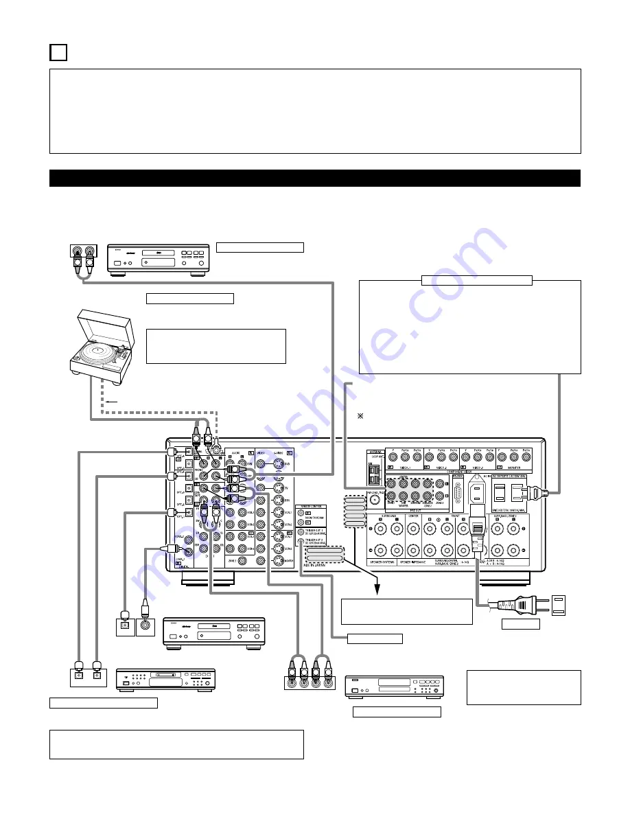
Connecting the audio components

• When making connections, also refer to the operating instructions of the other components.

CD player

Connecting a CD player

Connect the CD player’s analog output
jacks (ANALOG OUTPUT) to this unit’s CD
jacks using pin plug cords.

Connecting a turntable

Connect the turntable’s output cord to the AVR-
2805/985’s PHONO jacks, the L (left) plug to the L
jack, the R (right) plug to the right jack.

NOTE:

This unit cannot be used with MC cartridges
directly. Use a separate head amplifier or step-up
transformer.

If humming or other noise is generated when the
ground wire is connected, disconnect the ground
wire.

Turntable 

(MM cartridge)

Ground wire

Connecting the pre-out jacks

Use these jacks if you wish to connect external power amplifier(s) to
increase the power of the front, center and surround sound channels, or
for connection to powered loudspeakers.

To use Surround back with one speaker, connect the speaker to
SURR. BACK L CH.

AC OUTLETS

• SWITCHED

(total capacity – 120 W (1 A.))

The power to these outlets is turned on and off in conjunction with the
POWER operation switch on the main unit, and when the power is switched
between on and standby from the remote control unit.
No power is supplied from these outlets when this unit’s power is at standby.
Never connect equipment whose total capacity is above 120 W (1 A.).

NOTE:

Only use the AC OUTLETS for audio equipment. Never use them for hair
driers, TVs or other electrical appliances.

Connecting the AC OUTLETS

AC CORD

AC 120 V, 60 Hz

Connecting a tape deck

Connections for recording:

Connect the tape deck’s recording input jacks (LINE IN or REC) to this unit’s tape
recording (CDR/TAPE OUT) jacks using pin plug cords.

Connections for playback:

Connect the tape deck’s playback output jacks (LINE OUT or PB) to this unit’s tape
playback (CDR/TAPE IN) jacks using pin plug cords.

CD recorder or Tape deck

Route the connection cords, etc., in such a
way that they do not obstruct the ventilation
holes.

MD recorder, CD recorder or other component
equipped with digital input/output jacks

CD player or other component
equipped with digital output jacks

Connecting the DIGITAL jacks

Use these for connections to audio equipment with digital output. Refer to “Setting the
Digital in Assignment”. (See page 37)

NOTES:

• Use 75 

/ohms cable pin cords for coaxial connections.

• Use optical cables for optical connections, removing the cap before connecting.

NOTE:

If humming noise is generated by a
tape deck, etc., move the tape deck
away.

TRIGGER OUT

Turn the DC 12V voltage on and off for the individual functions.
For details, see “Setting the Trigger Setup”. (See page 44)

Summary of Contents for AVR 2805 - AV Receiver

Page 1: ...preciate your purchase of the AVR 2805 985 2 To be sure you take maximum advantage of all the features the AVR 2805 985 has to offer read these instructions carefully and use the set properly Be sure to keep this manual for future reference should any questions or problems arise SERIAL NO PLEASE RECORD UNIT SERIAL NUMBER ATTACHED TO THE REAR OF THE CABINET FOR FUTURE REFERENCE ...

Page 2: ...ements of the Canadian Interference Causing Equipment Regulations Cet appareil numérique de la classe B respecte toutes les exigences du Règlement sur le matériel brouilleur du Canada WARNING TO PREVENT FIRE OR SHOCK HAZARD DO NOT EXPOSE THIS APPLIANCE TO RAIN OR MOISTURE 2 NOTE ON USE OBSERVATIONS RELATIVES A L UTILISATION Avoid high temperatures Allow for sufficient heat dispersion when installe...

Page 3: ...e ANSI NFPA 70 provides information with regard to proper grounding of the mast and supporting structure grounding of the lead in wire to an antenna discharge unit size of grounding conductors location of antenna discharge unit connection to grounding electrodes and requirements for the grounding electrode See Figure A 16 Lightning For added protection for this product during a lightning storm or ...

Page 4: ...1 2 BEFORE USING CAUTIONS ON INSTALLATION Pay attention to the following before using this unit Moving the set To prevent short circuits or damaged wires in the connection cords always unplug the power cord and disconnect the connection cords between all other audio components when moving the set Before turning the power switch on Check once again that all connections are proper and that there are...

Page 5: ...ect Mode AL24 Processing The AVR 2805 985 is equipped with a pure direct mode allowing the effects of the video and digital circuitry to be shut down when playing CDs or records to achieve the ideal environment for analog playback resulting in extremely high quality music playback It is also equipped with AL24 processing which compensates the input digital data to produce the near analog waveforms...

Page 6: ... power of the front center and surround sound channels or for connection to powered loudspeakers To use Surround back with one speaker connect the speaker to SURR BACK L CH AC OUTLETS SWITCHED total capacity 120 W 1 A The power to these outlets is turned on and off in conjunction with the POWER operation switch on the main unit and when the power is switched between on and standby from the remote ...

Page 7: ...er or a video disc player VDP DVD Connect the video disc player s video output jack VIDEO OUTPUT to the yellow DVD IN jack using a 75 Ω ohms video coaxial pin plug cord Connect the video disc player s analog audio output jacks ANALOG AUDIO OUTPUT to the DVD IN jacks using pin plug cords VDP can be connected to the VDP jacks in the same way AUDIO VIDEO Monitor TV MONITOR OUT Connect the TV s video ...

Page 8: ... S Video connection cord VDP can be connected to the VDP jacks in the same way It is also possible to connect a video disc player DVD player video camcorder game machine etc to the V AUX jacks Connecting a monitor TV MONITOR OUT Connect the TV s S video input S VIDEO INPUT to the MONITOR OUT jack using a S jack connection cord S VIDEO Monitor TV Connecting a TV or DBS tuner Connect the TV s or DBS...

Page 9: ...deo signal to the S Video and composite video signal is not possible so when not using the component video monitor output terminal connect the player using the S Video or composite video input terminal Cautions on the video conversion function When the component video terminals are used to connect the AVR 2805 985 with a TV or monitor projector etc and the video yellow or S video terminals are use...

Page 10: ... for proper grounding and in particular specifies that the cable ground shall be connected to the grounding system of the building as close to the point of cable entry as practical Notes Do not connect two FM antennas simultaneously Even if an external AM antenna is used do not disconnect the AM loop antenna Make sure AM loop antenna lead terminals do not touch metal parts of the panel L R L R R L...

Page 11: ...be used to play a different program source in ZONE2 the same time See page 67 The ZONE2 video out is only for the ZONE2 ZONE2 RC 616 INFRARED RETRANSMITTER Integrated pre main amplifier or power amplifier RC 617INFRARED SENSOR Extension jacks for future use L R OUTPUT INPUT AUX OUT B L R 2 ZONE2 SPEAKER OUT and PREOUT CONNECTIONS If another power amplifier or pre main integrated amplifier is conne...

Page 12: ...L R VIDEO OUT L OUTPUT OUTPUT LINE OUT DIGITAL OUT VIDEO OUT S VIDEO OUT VIDEO OUT LINE OUT S VIDEO OUT S VIDEO OUT L R L R L R Connecting a Video game component Connect the Video game component s output jacks to this unit s V AUX INPUT jacks Video game Video camera Connecting a video camera component Connect the video camera component s output jacks to this unit s V AUX INPUT jacks ...

Page 13: ... to damage The protector circuit may be activated if the set is played for long periods of time at high volumes when speakers with an impedance lower than the specified impedance are connected Connection the speaker terminals 1 Loosen by turning counterclockwise 2 Insert the cord 3 Tighten by turning clockwise Connecting banana plugs banana plug Turn clockwise to tighten then insert the banana plu...

Page 14: ... with the wiring of the speaker cables or input cables and wait for the unit to cool down if it is very hot Improve the ventilation condition around the unit and switch the power back on If the protection circuit is activated again even though there are no problems with the wiring or the ventilation around the unit switch off the power and contact a DENON service center Protector circuit The prote...

Page 15: ... i PURE DIRECT button 62 o FRONT SPEAKER button 58 0 SURROUND BACK button 73 1 DIMMER button 64 2 STATUS button 64 3 V AUX input jacks 12 4 SETUP MIC jack 21 5 SURROUND MODE button 78 6 SURROUND PARAMETER button 70 80 7 SELECT knob 60 63 69 74 78 80 8 TONE DEFEAT button 63 9 TONE CONTROL button 63 80 0 MASTER VOLUME control 60 1 MASTER VOLUME indicator 60 2 Display 3 Remote control sensor REMOTE S...

Page 16: ...ings of the front speakers y Decoder indicator This lights when each decoder is operating u MASTER VOLUME indicator This displays the volume level The Setup item number is displayed in System Setup i MULTI ZONE indicator ZONE2 mode is selected in ZONE2 REC SELECT o REC OUT SOURCE indicator REC OUT mode is selected in ZONE2 REC SELECT 0 AL24 indicator The AL24 indicator lights when the PURE DIRECT ...

Page 17: ...ote control signal transmitter 48 ZONE 2 buttons 67 MUTING button 63 MODE SELECT button 49 RETURN button 51 52 FRONT SPEAKER button 58 LED indicator 50 57 Cursor buttons 18 SYSTEM SETUP SETUP button 18 47 ON SCREEN DISPLAY button 64 73 TEST TONE button 68 USE LEARN button 53 56 INPUT MODE selector buttons 59 61 SURROUND BACK button 73 CH SELECT ENTER button 18 68 69 SURROUND PARAMETER button 70 80...

Page 18: ...for the different channels in order to obtain optimum effects Front Sp Large Center Sp Surround Sp Subwoofer Small Small Yes Front L R Center Surround L R Subwoofer 12 ft 3 6 m 12 ft 3 6 m 10 ft 3 0 m 12 ft 3 6 m Front L Front R Center Surround R Surround Back R Subwoofer 0 dB 0 dB 0 dB 0 dB 0 dB 0 dB Surround Back Sp Small 2spkrs 3 Delay Time This parameter is for optimizing the timing with which...

Page 19: ...controls on the remote control unit or main unit are operated A setting to prevent flickering On Screen Display ON Mode 1 5 Auto Tuner Presets FM stations are received automatically and stored in the memory A1 A8 B1 B8 C1 C8 D1 D8 E1 E8 87 5 89 1 98 1 107 9 90 1 90 1 90 1 90 1 MHz 520 600 1000 1400 1500 1710 kHz 90 1 90 1 MHz 90 1 MHz 90 1 MHz 90 1 MHz F1 F8 90 1 MHz G1 G8 90 1 MHz 4 7 Setup Lock ...

Page 20: ...1 2 Check that all the connections are correct then turn on the main unit s power Setup will not be possible when the unit is set to Pure Direct ON or when the headphones are plugged in Therefore please cancel the mode or reverse the condition Display the System Setup Menu Remote control unit A u t o S e t R o o m E Q S y s t e m S e t u p NOTES The System Setup menu composition is of a layered de...

Page 21: ...r connection mode polarity and bass reproduction ability w This sets the optimum delay time from each speaker corresponding to the listening position e This sets the volume that is output from each speaker r This sets the frequency response of each speaker NOTE A loud test tone is output during the measurement Please consider this should you be planning night time measurements and consider not all...

Page 22: ...mote control unit A u t o S e t u p A u t o S e t R o o m E Q Remote control unit q Select the Power Amp Assign setting w Select Surround Back or ZONE2 Remote control unit Remote control unit P A m p S B A u t o S e t u p 4 q Select the Start Remote control unit S t a r t A u t o S e t u p Remote control unit 2 Display the Auto Setup screen w Press the Cursor left button NOTE When ZONE2 is selecte...

Page 23: ...ts NOTES Measurement is canceled when MASTER VOLUME is operated while the Auto Setup is performed Set the volume to halfway and set the crossover frequency to the maximum or Low pass filter off if your subwoofer speaker can adjust the output volume and the crossover frequency q This screen will be displayed when the speakers required for producing suitable reproduction have not been detected The f...

Page 24: ...nit Select from the following three items based on the measurement results Set with the checked measurement value Perform the measurement again Cancel the checked measurement value S t o r e A u t o S e t u p 4 Remote control unit When the Store is selected all parameters are stored up When the Retry is selected it measures again 5 Remote control unit NOTE When measurements have been made using th...

Page 25: ...s Remote control unit 4 Select the frequency Remote control unit 5 Use the cursor left and right buttons to adjust the Gain level Each frequency can be adjusted the range from 6dB to 6dB in 0 5dB step Remote control unit 6 Enter the setting The Auto Setup Room EQ Menu reappears Remote control unit M a n u a l E Q S e t u p A u t o S e t R o o m E Q 6 3 H z 0 0 d B M a n u a l E Q S e t u p SB FL F...

Page 26: ...the front speakers Manual Selects the setting value that was set in the Manual EQ setup Display the Room EQ Setup screen Remote control unit S u r M o d e A L L R o o m E Q S e t u p 3 Select All or Assign All The Equalizer to all Surround mode is set as once Assign The Equalizer to each surround mode is to set individually Remote control unit 4 Remote control unit R o o m E Q N o r m a l R o o m ...

Page 27: ... e A u t o S e t R o o m E Q Perform the ON OFF setting of Room EQ when the surround mode is Direct or Pure Direct 2 Display the Direct Mode Setup screen Remote control unit 3 Select ON or OFF Remote control unit 4 Enter the setting The Auto Setup Room EQ Menu reappears Remote control unit R o o m E Q O F F D i r e c t M o d e ...

Page 28: ...ch pin jack Please ask the DENON Authorized Service Center about the usable microphone other than the option setup 2 Display the Mic Input Select screen Remote control unit 3 Select the Mic input jack or V AUX L jack Remote control unit 4 Enter the setting The Auto Setup Room EQ Menu reappears Remote control unit 1 6 Check the EQ parameter 1 Select EQ Parameter Check at the Auto Setup Room EQ Menu...

Page 29: ...Menu reappears 8 Select Exit and press the ENTER button at the Auto Setup Room EQ Menu screen The System Setup Menu reappears Remote control unit 3 Select the Equalizer curve Remote control unit 2 4 Display the parameter screen 5 Remote control unit Select the speaker channel Cross over Frequency and Subwoofer Mode Setup is not displayed when not using a subwoofer 6 Enter the Setting Remote contro...

Page 30: ... Sp Subwoofer Surround Sp Surround back Sp Remote control unit S p e a k e r C o n f i g S p e a k e r S e t u p Remote control unit Remote control unit Remote control unit F r o n t S p L a r g e S p e a k e r C o n f i g Remote control unit Parameters Large Select this when using speakers that have sufficient performance for reproducing bass sound below the frequency set for the Crossover Freque...

Page 31: ...nd listening position L4 Distance between surround back speakers and listening position L5 Distance between subwoofer and listening position L1 L2 L5 L3 L4 Center FR FL Subwoofer SL Listening position SR SBR SBL 2 3 4 5 Display the Delay Time screen Select the desired unit meters or feet Once Meters or Feet is selected in step 3 the Delay Time screen appears automatically Select the speaker to be ...

Page 32: ...stance is set to 12 feet for the center speaker 7 Enter the setting The Speaker Setup Menu reappears The AVR 2805 985 automatically sets the optimum surround delay time for the listening room NOTE If the distance unit is changed after the delay time is set the settings are reset to the factory default values see page 18 2 3 Setting the Channel Level Use this setting to adjust so that the playback ...

Page 33: ... selected Example When the volume is set to 11 5 dB while the test tone is being produced from the Front Lch speaker Flashing FL C FR SR SBR SBL SL SW SB 1spkr 2spkrs When the surround back speaker setting is set to 1spkr for Speaker Configuration this is set to SB Remote control unit Remote control unit T o n e S t a r t Y e s C h a n n e l L e v e l Remote control unit Remote control unit Remote...

Page 34: ... for adjusting channel levels within each surround mode See page 68 You can adjust the channel levels for each of the following surround modes PURE DIRECT DIRECT STEREO DOLBY DTS SURROUND 5 7 CH STEREO WIDE SCREEN SUPER STADIUM ROCK ARENA JAZZ CLUB CLASSIC CONCERT MONO MOVIE VIDEO GAME MATRIX and VIRTUAL Remote control unit 2 4 Setting the crossover frequency 1 Select the Crossover Frequency at th...

Page 35: ...cy Subwoofer mode 2 5 The subwoofer mode setting is only valid when LARGE is set for the front speakers and YES is set for the subwoofer in the Setting the type of speakers see page 30 When the LFE MAIN playback mode is selected the low frequency signal range of channels set to LARGE are produced simultaneously from those channels and the subwoofer channel In this playback mode the low frequency r...

Page 36: ...36 Setting the Input Setup 1 At the System Setup Menu select Input Setup Remote control unit I n p u t S e t u p S y s t e m S e t u p 2 Display the Input Setup Menu screen Remote control unit 3 ...

Page 37: ...trol unit NOTES The OPTICAL 3 4 jacks on the AVR 2805 985 s rear panel are equipped with an optical digital output jack for recording digital signals on a CD recorder MD recorder or other digital recorder Use this for digital recording between a digital audio source stereo 2 channel and a digital audio recorder Do not connect the output of the component connected to the OPTICAL 3 4 OUT jack on the...

Page 38: ... s operating instructions 15dB default recommended 0 5 10 or 15 can be selected Remote control unit E x t I n S W L e v I n p u t S e t u p S W L e v 1 5 d B E x t I n S W L e v Remote control unit Remote control unit Remote control unit 3 3 Setting the Component In Assign This setting assigns the color difference component video input jacks of the AVR 2805 985 for the different input sources 1 Se...

Page 39: ...t Mode w Select the mode as below Remote control unit Remote control unit AUTO When there are multiple input signals the input signals are detected and the input signal to be output from the video monitor output terminal is selected automatically in the following order component video S Video composite video Component The signal connected to the component video terminal is always played Video conv...

Page 40: ... available video stabilizer etc with a TBC time base corrector function between the AVR 2805 985 and the VTR or if your VTR has a TBC function turn it on Remote control unit 3 5 Auto Tuner Presets Use this to automatically search for FM broadcasts and store up to 56 stations at preset channels A1 to 8 B1 to 8 C1 to 8 D1 to 8 E1 to 8 F1 to 8 and G1 to 8 NOTE If an FM station cannot be preset automa...

Page 41: ...EFEAT ON 4 4 2 Setting the Dolby Digital Setup Sets the down mixing method when not using a center speaker or surround speakers OFF The dynamic range is not compressed ON The dynamic range is compressed automatically according to the combination of speakers being used 1 Select Dolby Digital Setup at the Advanced Playback Menu 3 Select ON if you want to use the Compression OFF if you do not want to...

Page 42: ... DIRECT mode the surround mode does not change even if the input signal is changed 1 Select Auto Surround Mode at the Advanced Playback Menu Remote control unit A u t o S u r r o u n d A d v a n c e d P l a y Remote control unit 2 Press the ENTER button Display the Auto Surround Mode screen 3 Select ON if you want to use the auto surround mode OFF if you do not want to use it 4 Enter the setting T...

Page 43: ...ng the Power Amplifier Assignment Remote control unit P A m p A s s i g n O p t i o n S e t u p S B a c k P A m p A s s i g n Remote control unit 4 Enter the setting The Option Setup Menu reappear Remote control unit Remote control unit 2 Press the ENTER button Display the Power Amp Assign screen 2 Display the Zone2 Vol Level screen Remote control unit Set the Zone2 pre out output level adjustment...

Page 44: ...a b l e Z o n e 2 V o l L e v Remote control unit Remote control unit 5 3 5 4 Setting the Trigger Out Setup Set the Trigger Out output 1 for the different input sources 1 2 3 Select Trigger Out 1 Setup at the Option Setup Menu Display to the Trigger Out 1 Setup screen Select the Zone MAIN or Zone2 T r i g g e r O u t 1 O p t i o n S e t u p Remote control unit Z O N E M A I N T r i g g e r O u t 1...

Page 45: ... t u p 2 Display the On screen display setup screen Remote control unit 3 Select ON or OFF Remote control unit O N O F F O N O n S c r e e n M u t i n g L e v e l O p t i o n S e t u p 5 5 Setting the Muting Level 1 Select Muting Level at the Option Setup Menu 3 Select the desired setting Remote control unit Remote control unit d B M u t i n g L e v e l Remote control unit 4 Enter the setting The ...

Page 46: ... Option Setup Menu 2 Display the Setup Lock screen 3 Select ON to lock the system setup settings 4 Press the ENTER button to finalize the setting and exit the Option setup mode When the setup lock function is activated the settings listed below cannot be changed and SETUP LOCKED is displayed when related buttons are operated System setup settings Surround parameter settings Tone control settings C...

Page 47: ... jack E E C C Video signal output to VIDEO MONITOR OUT jack yellow C C C E Video signal output to Color Difference Component Video MONITOR OUT jack C C C C On screen display signal output C Signal E No signal C On screen signals output E On screen signals not output NOTE When a component video signal is input and when the Video Input Mode is set to the component fixed mode at Input setup the on sc...

Page 48: ... old one Do not use two different types of batteries Do not short circuit disassemble heat or dispose of batteries in flames Remove the batteries from the remote control unit when you do not plan to use it for an extended period of time If the battery fluid should leak carefully wipe the fluid off the inside of the battery compartment and insert new batteries When replacing the batteries have the ...

Page 49: ...p 1 Play 8 9 Auto search to beginning of track 3 Pause DISC SKIP for CD changers only 6 Rewind 7 Fast forward 2 Stop 1 Forward play 3 Pause 0 Reverse play A B Switch between sides A and B 3 MD recorder MD CD recorder CDR system buttons 6 7 Manual search forward and reverse 2 Stop 1 Play 8 9 Auto search to beginning of track 3 Pause Default setting CDR 4 Tuner system buttons TUNING Tuning up down B...

Page 50: ...ufacture this function cannot be used for some models even if the your device is listed on the included list of preset codes Some manufacturers use more than one type of remote control code Refer to the included list of preset codes to change the number and check it out The preset memory can be set for one component only among the following CDR MD DVD VDP and DBS CABLE The included remote control ...

Page 51: ... ON SOURCE 6 7 Manual search forward and reverse 2 Stop 1 Play 8 9 Auto search to beginning of track 3 Pause 0 9 10 10 key DISC SKIP Disc skip for DVD changer only DISPLAY Display MENU Menu RETURN Return SETUP Setup ENTER Enter ª 0 1 Cursor up down left and right 2 Video disc player VDP system buttons POWER Power on standby ON SOURCE 6 7 Manual search forward and reverse 2 Stop 1 Play 8 9 Auto sea...

Page 52: ...l Channels POWER Power on standby ON SOURCE MENU Menu ª 0 1 Cursor up down left and right ENTER Enter CHANNEL Switch channels 0 9 10 Channels TV VCR Switch between TV and video player TV VOL Volume up down DISPLAY Switch display RETURN Return NOTES For this CD CDR MD and TAPE components buttons can be operated in the same way as for Denon audio components The television can be operated in the DVD ...

Page 53: ...hat cannot be learned is pressed To cancel press the USE LEARN button 4 Point the remote control units directly at each other and press and hold in the button on the other remote control unit which you want to learn 5 The mode button and the LEARNED TX indicator lights release the button on the other remote control unit The mode button and the LEARNED TX indicator start flashing again 6 To learn o...

Page 54: ...t source turn on the monitor TV s power turn on the source component s power and set the source to the play mode all at a signal button 3 Press the mode buttons of the equipment that is to be registered to System Call 4 Press the buttons whose remote control signals you want to store one by one 5 Repeat steps 3 and 4 to register the desired buttons 6 Press the CALL1 or CALL2 button and register Sy...

Page 55: ...n the TV mode the CD mode s PLAY STOP MANUAL SEARCH AUTO SEARCH PAUSE and DISC SKIP buttons signals are sent in the TV mode 2 Making the punch through setting 1 2 Press the power ON SOURCE button and the OFF button at the same time The LEARNED TX indicator flashes Press the 1 play button TV and DBS CABLE mode buttons and LEARNED TX indicator flash 1 3 2 1 1 4 3 Press the mode button of the equipme...

Page 56: ...ashes 2 Press the mode button of the equipment that is to be reset Mode button and LEARNED TX indicator flash 3 Hold for 4 seconds or longer the mode button of the equipment that is to be reset and the ON SOURCE button The mode button and the LEARNED TX indicator will again flash and the learned remote control signal of the selected equipment will be deleted 4 Press the USE LEARN button ...

Page 57: ...tons and LEARNED TX indicator flash 3 Press the mode button of the equipment TV or DBS CABLE that is to be reset The CD CDR MD TAPE DVD VDP and VCR mode buttons and LEARNED TX indicator will flash 4 Press the mode button of the equipment that is to be reset again During the resetting operation the selected mode button and the LEARNED TX indicator will light they will return to steady state upon co...

Page 58: ...ontrol unit OFF The power turns off and indicator is off In this position the power cannot be turned on and off from the remote control unit 4 Turn on the power Press the POWER ON STANDBY switch button ON STANDBY Main unit When pressed the power turns on and the display lights The sound is muted for several seconds after which the unit operates normally When pressed again the power turns off the s...

Page 59: ...igital signals is detected the signals input to the digital input jacks are identified and decoding and playback are performed automatically in DTS Dolby Digital or PCM 2 channel stereo format If no digital signal is being input the analog input jacks are selected Use this mode to play Dolby Digital signals w PCM exclusive PCM signal playback mode Decoding and playback are only performed when PCM ...

Page 60: ...be sure to connect the source component to the digital input jacks OPTICAL COAXIAL and set the input mode to DTS Input mode display In the AUTO mode In the DIGITAL PCM mode In the DIGITAL DTS mode In the ANALOG mode Depending on the input signal Input signal display DOLBY DIGITAL DTS PCM The indicator lights when digital signals are being input properly If the indicator does not light check whethe...

Page 61: ...E OUT SUBWOOFER jack 2 Cancelling the external input mode To cancel the external input EXT IN setting press the input mode AUTO PCM DTS or ANALOG button to switch to the desired input mode See page 59 MODE Main unit Remote control unit When the input mode is set to the external input EXT IN the surround mode DIRECT STEREO STANDARD 5 7CH STEREO WIDE SCREEN or DSP SIMULATION cannot be set NOTES In p...

Page 62: ...ages In this mode the audio signals bypass such circuits as the tone circuit and are transmitted directly resulting in good quality sound 3 STEREO mode Use this mode to adjust the tone and achieve the desired sound while watching images NOTES The system setup function cannot be used when the PURE DIRECT mode is set To use the system setup function cancel the PURE DIRECT mode The ZONE2 video output...

Page 63: ...n steps of 1 dB 2 Listening over headphone 1 Plug the headphone plug into the jack Connect the headphone to the PHONES jack The pre out output including the speaker output is automatically turned off when headphone are connected 1 PHONES 2 1 3 Main unit Remote control unit BASS TREBLE 3 If you do not want the bass and treble to be adjusted turn on the tone defeat mode The signals do not pass throu...

Page 64: ...e display The display brightness changes in four steps bright medium dim and off by pressing the main unit s DIMMER button repeatedly 11 Main unit Remote control unit Multi source recording playback Playing one source while recording another REC OUT mode 1 Press the ZONE2 REC button ZONE 2 REC SELECT 2 With RECOUT SOURCE displayed turn the FUNCTION knob to select the source you wish to record When...

Page 65: ... output use high quality pin plug cords and wire in such a way that there is no humming or noise For instructions on installation and operation of separately sold devices refer to the devices operating instructions When the PURE DIRECT mode is set for the main zone no signals are output to the ZONE2 video terminals Signals are output from the ZONE2 video terminals even when ZONE2 is set to OFF MUL...

Page 66: ...s adjustable ZONE2 and composite video output terminals as the ZONE2 output terminals This unit DVD player Input RC 616 Monitor Monitor MAIN ZONE 5 1 channel systems ZONE2 SPEAKER OUT ZONE 2 VIDEO OUT SYSTEM REMOTE CONTROL UNIT RC 974 C FL FR SL SW SR B RC 617 PROGRAMMABLE REMOTE CONTROL UNIT ZONE 2 ROOM TO ROOM REMOTE CONTROL SYSTEM separately sold control line MULTI SOURCE AUDIO signal cable SPE...

Page 67: ...button To turn off the ZONE2 mode press the ZONE2 OFF button Remote control unit 3 Press the input source button The ZONE2 source switches directly 4 The output level of the ZONE2 OUT terminals can be controlled using the VOLUME and buttons on the remote control unit The output level of ZONE2 OUT can be controlled only if ZONE2 vol level is set Variable at Zone2 Control in System Setup Menu see pa...

Page 68: ...ust so that the volume of the test tones is the same for all the speakers After adjusting using the test tones adjust the channel levels either according to the playback sources or to suit your tastes as described below 1 3 2 3 After completing the adjustment press the TEST TONE button again 1 Select the speaker level you want to adjust Remote control unit 2 Adjust the level of the selected speake...

Page 69: ...ly after adjusting the fader the fader adjustment values are cleared so adjust the fader again Dolby Pro Logic IIx Pro Logic II mode 1 Select the Dolby Pro Logic IIx mode 2 Play a program source with the mark For operating instructions refer to the manuals of the respective components This is only displayed when setting the fader control Main unit 1 3 5 1 4 6 1 3 7 4 5 6 7 1 2 FL C FR SR SBR SBL S...

Page 70: ...parameters are set using the buttons on the main unit stop operating buttons after completing the settings The settings are automatically finalized and the normal display reappears after several seconds When the settings are made using the buttons on the remote control unit press the ENTER or SURROUND PARAMETER button to finish Display When the SB CH OUT parameter is set to ON Set SP Back at the s...

Page 71: ... set in 8 steps from 0 to 7 ProLogic The Pro Logic mode offers the same robust surround processing as original Pro Logic in case the source contents is not of optimum quality Game The Game mode for playing games The game mode can only be used with 2 channel audio sources DTS NEO 6 mode 1 Select the DTS NEO 6 mode 2 Play a program source 1 3 5 1 4 6 1 3 7 7 4 5 6 The DTS NEO 6 Cinema or Music mode ...

Page 72: ...nd field CENTER IMAGE 0 0 to 1 0 default 0 3 The center image parameter for adjusting the expansion of the center channel in the DTS NEO 6 MUSIC mode has been added Dolby Digital mode only with digital input and DTS Surround mode only with digital input 1 Select the input source Playback with a digital input q Select an input source set to digital COAXIAL OPTICAL see page 37 FUNCTION Remote contro...

Page 73: ...mote control unit s ON SCREEN button SIGNAL Displays the type of signal DTS DOLBY DIGITAL PCM etc fs Displays the input signal s sampling frequency FORMAT Displays the input signal s number of channels Number of front channels Number of surround channels LFE on off SURROUND is displayed for 2 channel signal sources recorded in Dolby Surround OFFSET Displays the dialog normalization offset value FL...

Page 74: ... future This is a function for automatically playing in the 6 1 channel mode using the surround back speakers if the software is recorded in DTS ES or in the normal 5 1 channel mode without using the surround back speakers when the software is not recorded in DTS ES OFF Set the OFF mode to perform 6 1 channel playback with conventional 5 1 channel sources or sources on which the identification sig...

Page 75: ...ing NOTE The audio delay setting does not apply when playing in the EXT IN mode or in the analog input direct mode or stereo mode TONE DEFEAT ON 1 q 1 w 1 e 1 e Remote control unit A u d i o D e l a y A d v a n c e d P l a y 5 Select Audio Delay at the Advanced Playback Menu Remote control unit 6 Switch to the Audio Delay adjustment screen Remote control unit 7 Set the delay time 0 ms 200 ms Remot...

Page 76: ... movie theaters are added to the surround channels The front left channel signals are output to the surround and surround back signal left channels the front right channel signals are output to the surround and surround back signal right channels and the in phase component of the left and right channels is output to the center channel Use this mode to enjoy stereo sound 8 9 MATRIX VIRTUAL Select t...

Page 77: ...rol unit When Default is selected and the cursor left button is pressed CINEMA EQ and D COMP are automatically turned off ROOM SIZE is set to medium EFFECT LEVEL to 10 DELAY TIME to 30ms and LFE to 0dB The ROOM SIZE expresses the expansion effect for the different surround modes in terms of the size of the sound field not the actual size of the listening room When playing PCM digital signals or an...

Page 78: ...rround mode while adjusting the surround parameters or tone control press the surround mode button then operate the selector NOTE When playing PCM digital signals or analog signals in the DOLBY PRO LOGIC IIx DTS NEO 6 modes and the input signal switches to a digital signal encoded in Dolby Digital the Dolby surround mode switches automatically When the input signal switches to a DTS signal the mod...

Page 79: ...he Room RQ Tone Control screen Remote control unit Remote control unit Remote control unit R O O M M e d i u m S u r r P a r a m e t e r E Q T O N E S u r r P a r a m e t e r 4 Select the Equalizer setting Remote control unit R o o m E Q O F F R o o m E Q T o n e R o o m E Q N o r m a l R o o m E Q T o n e OFF Normal Front Manual Flat NOTES The equalizer setting of Normal Flat and Front can be sel...

Page 80: ...m E Q O F F S u r r P a r a m e t e r 3 Select the Equalizer setting SELECT Main unit Operate the tone control from the main unit 1 The tone switches as follows each time the TONE CONTROL button is pressed Main unit 1 TREBLE 0 BASS 2 1 B a s s 0 d B T o n e C o n t r o l 2 Select with the name of the volume to be adjusted and adjust the level To increase the bass or treble Turn the control clockwi...

Page 81: ...of each speaker to the characteristics of the front speakers Manual Selects the setting value that was set in the Manual EQ setup 2 Surround modes and parameters C C E C C C C E C C C C C C C C C C C C E C C C E C C C C C C C C C C C C Signal Adjustable E No signal B Turned on or off by speaker configuration setting C Able E Unable Only for 2 ch contents Channel output FRONT L R CENTER SURROUND L ...

Page 82: ... C 0dB C 0dB When playing Dolby Digital and DTS signals MODE C Able E Unable E E E E E E E E E E E E E E E E C 30ms E E E E C OFF C OFF E E E E E E E E E E E E E C Adjustable E Not adjustable SURROUND PARAMETER EFFECT LEVEL PANORAMA DELAY TIME DIRECT PURE DIRECT STEREO EXTERNAL INPUT DOLBY PRO LOGIC II DOLBY PRO LOGIC II x DTS NEO 6 DOLBY DIGITAL SURROUND DTS SURROUND 5 7CH STEREO WIDE SCREEN SUPE...

Page 83: ...the remote control unit is set to AMP or TUNER FUNCTION 2 Watching the display press the BAND button to select the desired band AM or FM 3 Press the MODE button to set the manual tuning mode Check that the display s AUTO indicator turns off Main unit Remote control unit Remote control unit Remote control unit 4 Press the TUNING or button to tune in the desired station The frequency changes continu...

Page 84: ...5 Press the MEMORY button again to store the station in the preset memory Remote control unit Remote control unit To preset other channels repeat steps 2 to 5 A total of 56 broadcast stations can be preset 8 stations channels 1 to 8 in each of blocks A to G The preset broadcast stations can be checked on the on screen display 1 Press the ON SCREEN button repeatedly until the Tuner Preset Stations ...

Page 85: ...ted 15 INITIALIZATION OF THE MICROPROCESSOR When the indication of the display is not normal or when the operation of the unit does not shows the reasonable result the initialization of the microprocessor is required by the following procedure 1 Switch off the unit using the main unit s power operation switch 2 Hold the following INPUT MODE button and ANALOG button and turn the main unit s power o...

Page 86: ...cooled down turn the power back on 13 4 14 4 14 Sound produced only from one channel Incomplete connection of speaker cords Incomplete connection of input output cords Connect securely Connect securely 13 6 14 Positions of instruments reversed during stereo playback Reverse connections of left and right speakers or left and right input output cords Check left and right connections 13 The on screen...

Page 87: ...ncreased to four or eight or speakers with bipolar or dipolar properties are used Other types of audio These signals are designed to recreate a 360 sound field using three to five speakers In this case the speakers should surround the listener from all sides to create a uniform sound field from 360 Ideally the surround speakers should function as point sound sources in the same way as the front sp...

Page 88: ... Movement of acoustic image from SR to SL Change of positioning and acoustic image with 6 1 channel systems Movement of acoustic image from SR to SB to SL 2 Number of surround back speakers Though the surround back channel only consists of 1 channel of playback signals for 6 1 channel sources DTS ES etc we recommend using two speakers When using speakers with dipolar characteristics in particular ...

Page 89: ...poses Use these examples as guides to set up your system according to the type of speakers used and the main usage purpose 1 DTS ES compatible system using surround back speakers 1 Basic setting for primarily watching movies This is recommended when mainly playing movies and using regular single way or 2 way speakers for the surround speakers 2 Setting for primarily watching movies using diffusion...

Page 90: ...igital output jacks Playback method reference page 1 Please use a commercially available adapter when connecting the Dolby Digital RF output jack of the LD player to the digital input jack Please refer to the instruction manual of the adapter when making connection 2 Some DVD digital outputs have the function of switching the Dolby Digital signal output method between bit stream and convert to PCM...

Page 91: ...S Also never switch the input mode to ANALOG or PCM during playback The same holds true when playing CDs or LDs on a DVD player or LD DVD compatible player For DVDs the DTS signals are recorded in a special way so this problem does not occur 2 The signals provided at the digital outputs of a CD or LD player may undergo some sort of internal signal processing output level adjustment sampling freque...

Page 92: ...aims than with conventional 5 1 or 6 1 channel systems In addition the bit stream format is 100 compatible with conventional DTS signals so the effect of the Matrix 6 1 format can be achieved even with 5 1 channel signal sources Of course it is also possible to play DTS ES Matrix 6 1 encoded sources with a DTS 5 1 channel decoder When DTS ES Discrete 6 1 or Matrix 6 1 encoded sources are decoded w...

Page 93: ...d using DTS 96 24 can be played in high sampling frequency multiple channel audio with such normal media as DVD videos and CDs Thus with DTS 96 24 the same 96 kHz 24 bit multi channel surround sound as with DVD Audio can be achieved while viewing DVD Video images on a conventional DVD Video player 1 Furthermore with DTS 96 24 compatible CDs 88 2 kHz 24 bit multi channel surround can be achieved us...

Page 94: ... is in Direct or Pure Direct 4 Mic Input Select Set this to switch the Mic Input jack for use for Mic or V Aux L channel input jack Set this to switch the surround back channel s power amplifier for use for zone2 Set the Room EQ setting with All or Assign for each surround mode SURROUND BACK All Channel and Frequency 0dB All OFF Mic Speaker Setup Default settings 1 2 Speaker Configuration Channel ...

Page 95: ...NE 2 4 Advanced Playback 3 Auto Surround Mode Set the Auto surround mode function Auto Surround Mode ON 1 Audio Delay Set the audio delay to delay time the sound and synchronize it with the picture 0 ms Advanced Playback Default settings 2 Dolby Digital Setup Turn the audio compression on or off when down mixing Dolby Digital signals OFF C Signal Adjustable E No signal B Turned on or off by speake...

Page 96: ...E E E E E E E E E E E E E E C 3 C 3 E E E E E E E E E E E E E C OFF E E E E E E E E E E E E E E E E E SUBWOOFER ON OFF E E E C C C C C C C C C C C C C C E E C 0dB E C 0dB C 0dB C 0dB C 0dB C 0dB C 0dB C 0dB C Note1 C Note2 C 0dB C 0dB C 0dB C 0dB C 0dB C 0dB Parameter default values are shown in parentheses AFDM TONE CONTROL SB CH OUT MODE DIRECT PURE DIRECT STEREO EXTERNAL INPUT DOLBY PRO LOGIC I...

Page 97: ...EO S VIDEO VIDEO S VIDEO VIDEO 3 E VIDEO S VIDEO VIDEO 3 VIDEO INPUT Mode S VIDEO E C C E E C C MONITOR OUT Input signals COMPONENT VIDEO COMPONENT S VIDEO VIDEO COMPONENT E E E C C C C C E C E C E C E E E COMPONENT COMPONENT COMPONENT COMPONENT E E E E E E E E E E E E E E VIDEO INPUT Mode S VIDEO E C C E E C C MONITOR OUT Input signals COMPONENT VIDEO COMPONENT S VIDEO VIDEO S VIDEO E E E C C C C...

Page 98: ...ighting with 5 mV input Rated output Maximum output 150 mV 8 V Distortion factor 0 03 1 kHz 3 V 2 Video section Standard video jacks Input output level and impedance 1 Vp p 75 Ω ohms Frequency response 5 Hz 10 MHz 0 3 dB S video jacks Input output level and impedance Y brightness signal 1 Vp p 75 Ω ohms C color signal 0 286 Vp p 75 Ω ohms Frequency response 5 Hz 10 MHz 0 3 dB Color component video...

Page 99: ......

Page 100: ...Printed in Japan 511 4172 007 16 11 YUSHIMA 3 CHOME BUNKYO KU TOKYO 113 0034 JAPAN Telephone 03 3837 5321 ...

Reviews: