18
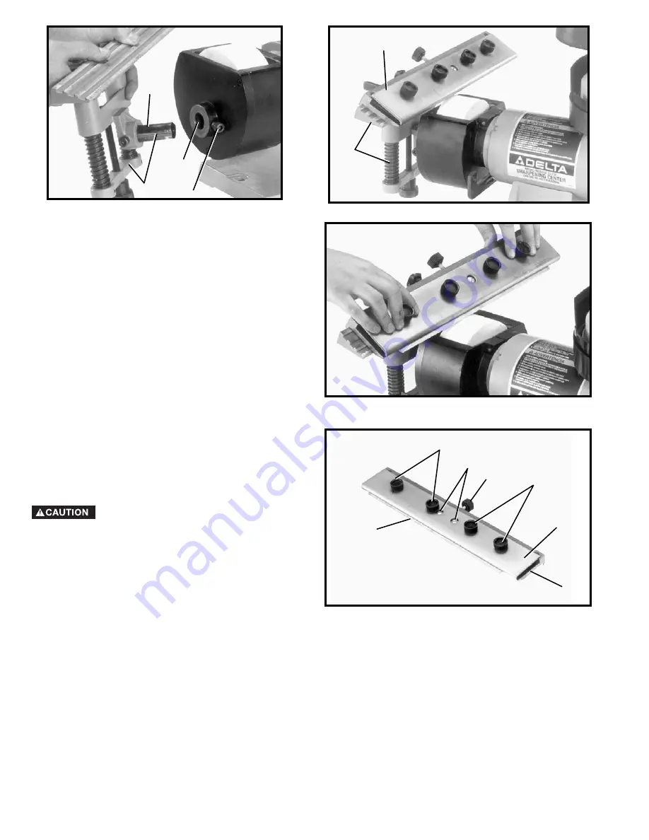
Fig. 49
Fig. 50
Fig. 51
Fig. 52
3.
Remove sliding tool rest and mounting post (E) Fig.
49, from the wet wheel side of the machine and
insert post of tool rest assembly into hole (F). Tighten
screw (G) into groove (J) of mounting post (E).
4.
Fig. 50, illustrates the sliding tool rest (E) assembled
to the dry wheel side of the machine with the knife
holder (H) positioned on the tool rest. All controls
and adjustments for the sliding tool rest are
explained in the section of this manual titled
“ASSEMBLING ACCESSORY 23-715 SLIDING
TOOL REST TO WET WHEEL.”
5.
Fig. 51, illustrates a rough grinding operation on a
planer knife using the dry wheel.
USING THE TOOL REST WITH
PLANER OR JOINTER KNIVES
1.
Loosen four lock knobs (A) Fig. 52 and two screws
(E) and carefully slide knife (B) between the top and
bottom pieces (C) and (D) of the sliding tool rest. It is
important that the bevel edge of the knife (B) is in the
down position. Also, be sure the back of the knife is
pushed in so it sits against the knife adjustment bar
inside the tool rest.
2.
Make sure knife (B) Fig. 52, protrudes out from the
top and bottom pieces (C) and (D) of the sliding tool
rest at least 5/16”. If it does not, rotate adjusting
knob (F) Fig. 50, clockwise to move the knife
outward or counterclockwise to move the knife in-
ward. When moving the knife inward, carefully push
the knife (B) inward with a piece of scrap wood while
turning the knob (F) counterclockwise. When you are
certain the knife protrudes 5/16” outward from the
sliding tool rest, tighten two screws (E) and four
knobs (A).
C A R E M U S T B E T A K E N W H E N
HANDLING PLANER OR JOINTER
K N I V E S , A S T H E C U T T I N G E D G E S A R E V E RY
SHARP.
WEAR PROTECTIVE GLOVES WHEN
HANDLING THE KNIVES.
J
E
F
G
H
E
A
B
A
E
F
D
C
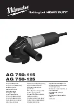
Summary of Contents for 23-710
Page 23: ...23 NOTES...


