


Delta Controls
Document Edition 4.2
Page 31 of 43
Box Mode affects how the flow damper functions in both VAV and VVT applications. Refer to page 15
for operating information on Box Mode, and page 16 regarding Controller Operation.
OWS Configuration
It is of course possible to configure the outputs via ORCAview OWS, rather than through the keypad
Configuration Menu at the BACstat. Variables AV21 to 23 are used to configure each of the three
outputs, but you must configure these variables in the proper sequence (refer to page 34 for further
information). For a complete list of these variables and other objects, refer to the Object table on page 9.
When configuring the BACstat through the keypad, configuration codes are automatically determined
for each of the output configuration variables. When using ORCAview OWS you manually enter an
appropriate configuration code for each variable (in the proper sequence). The configuration code for an
output is a combination of its
function
and
type
(as obtained from the tables on the previous page)
according to the following formula:
Output Configuration Code = Output
Function
Code + Output
Type
Code
For example: To configure Output 1 on a DNT-T221 as a direct acting analog output for first stage
heating, enter the number 10.4 into AV21 (where 10 is the
function
and 0.4 is the
type
, so 10 + 0.4
=10.4).
1.
B
INARY
O
UTPUTS
If the binary output is selected as M
UX
it simply transfers the value written to the corresponding variable
(AV1, AV2 or AV3) to the physical output. There is no delay.
If the binary output is controlled internally by the BACstat II, then it will have a delay-on that is
specified by its corresponding setup variable. This value is in seconds.
Physical Output
Associated AV
Delay Setup Variable
OP1
AV1
AV24
OP2
AV2
AV26
OP3
AV3
AV28
2.
P
ULSE
W
IDTH
M
ODULATION
O
UTPUTS
(PWM)
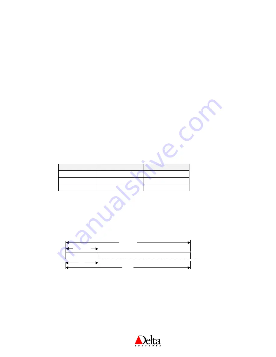
The Pulse Width Modulation scheme used on the BACstat II is applicable to the Belimo NM24
actuator.
An analog value is converted to a variable duty cycle pulse that has minimum and maximum pulse
times as determined by setup variables. For example, a Belimo PWM actuator uses a minimum value of
0.59 sec., and a maximum value of 2.93 sec. The O
N
portion of the pulse then stretches from 0% @
0.59 to 100% @ 2.93.
0.59 Sec.
2.93 Sec.
0%
100%
If the output using PWM is also configured as reverse acting then the output device will be considered
to be reverse acting (i.e., Normally Open) and the input value will be inverted internally before being
applied to the physical output. The actual action of the physical output will be direct.
If the PWM output is not being used for a Belimo device then the minimum and maximum values can
be changed to what ever is required. Also, Belimo actuators may be configured to use a 0.5 to 25.5
signal instead, which may be more suitable in many cases (i.e., variable values of 50 and 2550).


