


34
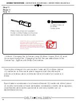
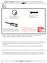
Step 10
Étape 10
Paso 10
ASSEMBLY INSTRUCTIONS •
INSTRUCTIONS DE MONTAGE • INSTRUCCIONES DE MONTAJE
ASSEMBLY INSTRUCTIONS •
INSTRUCTIONS DE MONTAGE • INSTRUCCIONES DE MONTAJE
1.Attach Changing Top Back (Part S) to the Right and Left Sides using (2)
35mm Bolts (Part DD) Tighten the bolts using the Ball End Screwdriver, then
ensure the bolts are tight using the Allen Wrench like shown on page 15.
M4 Ball End Screwdriver x1
M4 tournevis hexagonal
M4 destornillador hexagonal
M4 Allen Wrench x1
Clé Hexagonale
Llave Allen
DD. 35mm Bolt x2
Boulon 35mm
Perno 35mm
Fixer la partie postérieure du plan à langer (pièce S) au cotés droit et gauche
à l’aide de (2) boulons 35mm (pièce DD). Serrer les boulons à l’aide du
tournevis hexagonal, ensuite s’assurer que les boulons sont proprement serrés
à l’aide de la clé hexagonale comme montré en page 15.
Fijar la parte posterior del cambiador (pieza S) a los lados derecho e izquierdo
utilizando (2) pernos de 35mm (pieza DD). Apretar los pernos utilizando un
destornillador hexagonal. Asegurarse de que los pernos estén apretados
utilizando la llave Allen como se muestra en la página 15.


