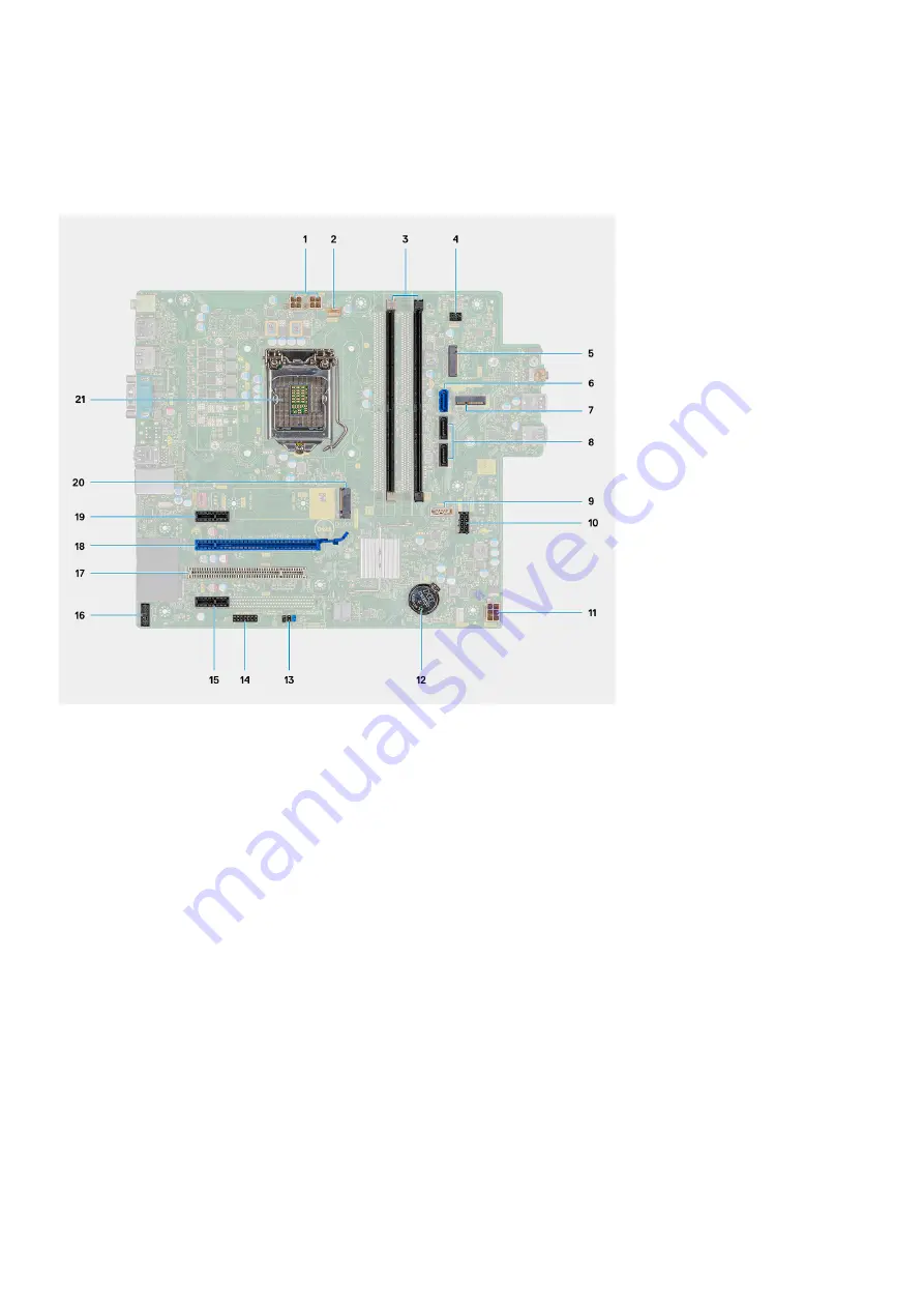
System board
System board layout
1. PSU power connector
2. Processor fan connector
3. Memory module slot
4. Power button connector
5. M.2 SSD card reader slot
6. SATA0 connector (blue)
7. M.2 WLAN slot
8. SATA1/2 connector (black)
9. SATA3 connector (white)
10. SATA power connector
11. ATX power connector
12. Coin-cell battery
13. CMOS_CLR/Password/Service_Mode jumper
14. APS/PETS connector (Debug)
15. PCIe x1 (Slot4)
16. LPC debug card connector
17. PCI-32 (Slot3)
18. PCIe x16 (Slot2)
19. PCIe x1 (Slot1)
20. M.2 2230/2280 SSD/Optane card connector
21. Processor socket
Removing the system board
Prerequisites
Before working inside your computer
.
2. Remove the
.
3. Remove the
.
4. Remove the
.
5. Remove the
6. Remove the
.
7. Remove the
8. Remove the
42
Disassembly and reassembly
Summary of Contents for Vostro 5890
Page 1: ...Vostro 5890 Service Manual Regulatory Model D28M Regulatory Type D28M004 August 2021 Rev A01 ...
Page 36: ...36 Disassembly and reassembly ...
Page 44: ...44 Disassembly and reassembly ...
Page 45: ...Disassembly and reassembly 45 ...
Page 47: ...Disassembly and reassembly 47 ...
Page 48: ...48 Disassembly and reassembly ...
Page 49: ...Disassembly and reassembly 49 ...


